Toms RCR 40 Trackracer

Status
Not open for further replies.
INSTALLING THE RADIATOR FANS.
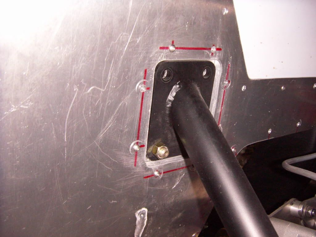
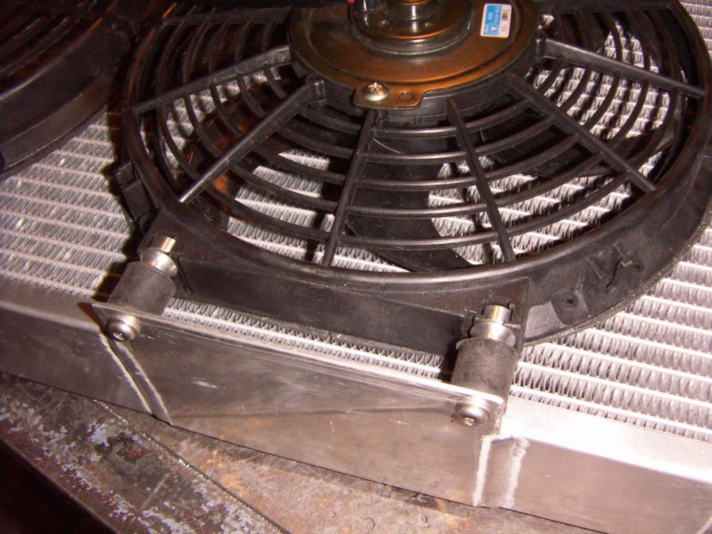
I had a friend o mine welding 4 additional tabs to the radiator. They are app 100mm wide and deep.
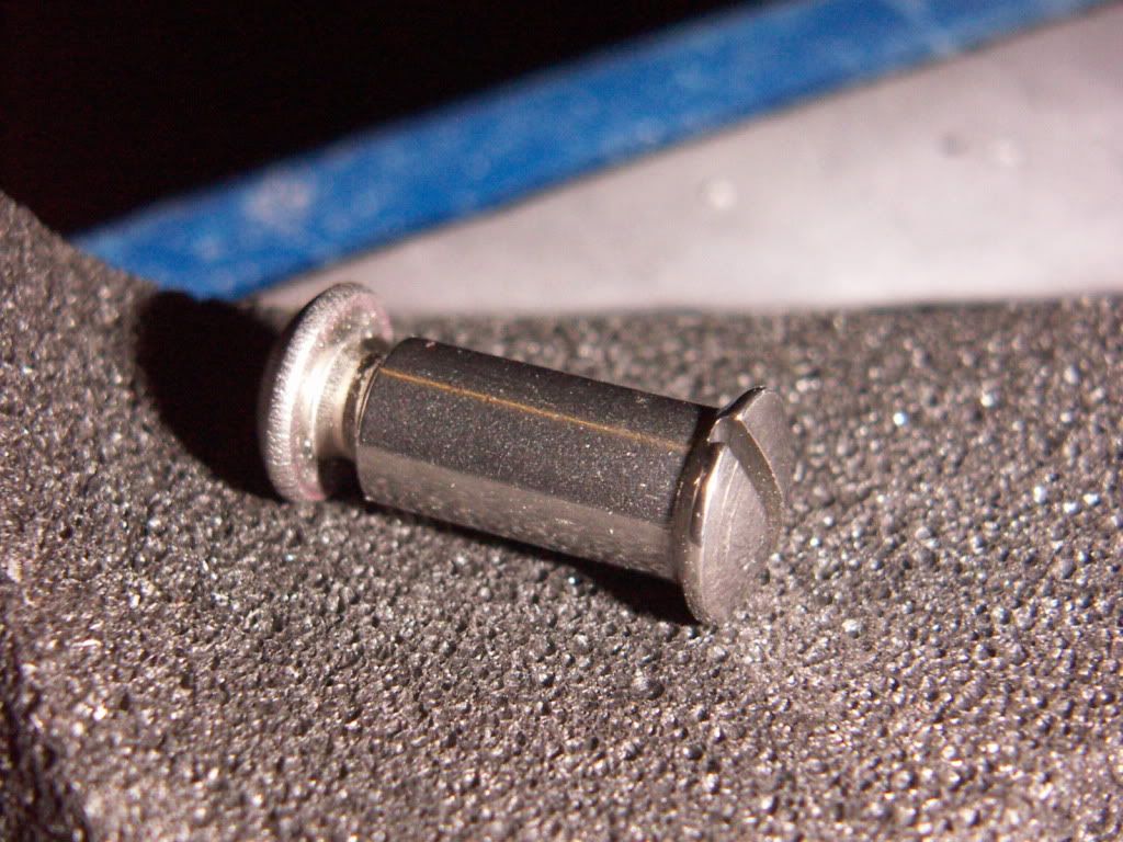
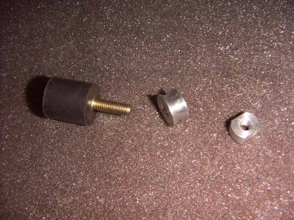
Sven my CNC friend made me some nice aluminium nuts and spacers fitting exactly in the slot recess of the fan. Mounting the whole assembly with elastic elements was done quickly.
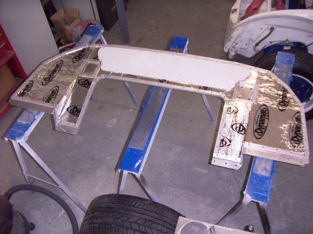
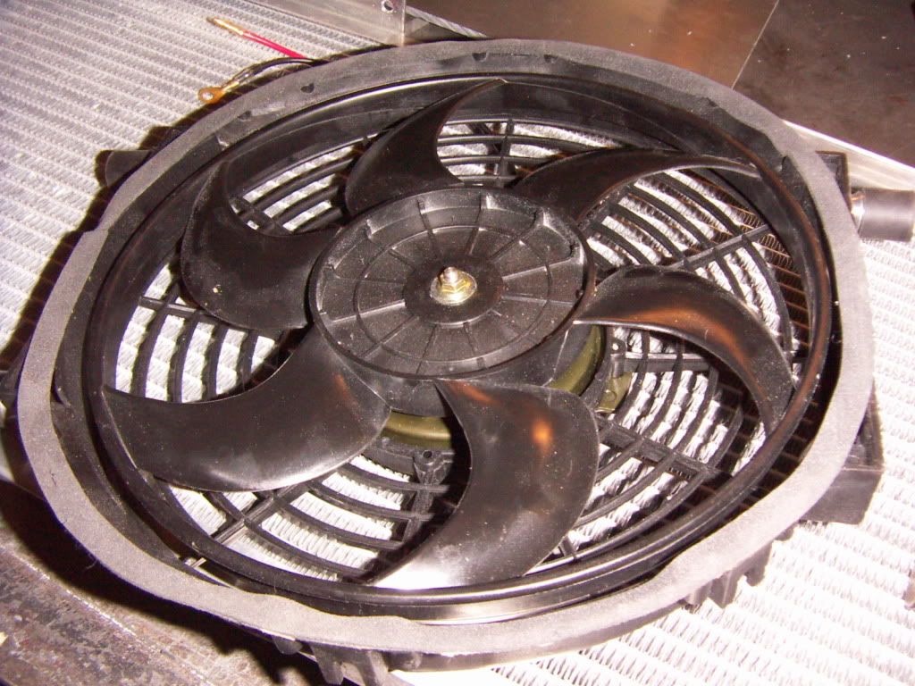
One thing: I think the fans work most efficient if the shroud of them seals tight to the radiator, in order to avoid any "false" air is sucked in from the side ( if one would mount them with a certain distance to the radiator surface). I used 2mmm selfadhesive foam to create a seal between the fan and the radiator. The mounting elements are than adjusted in a way, that they provide a little positive pressure on this foam seal.
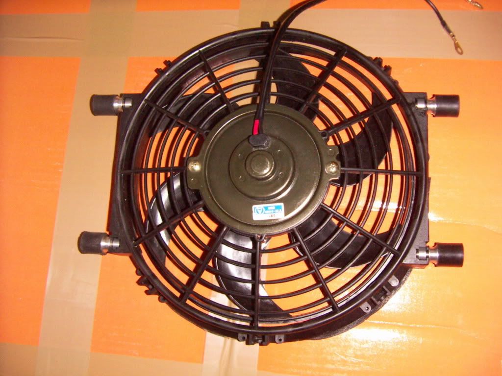
Mounting elements
PICT3754.jpg

installed on the fan
PICT3755.jpg

foam stripe seal
PICT3756.jpg

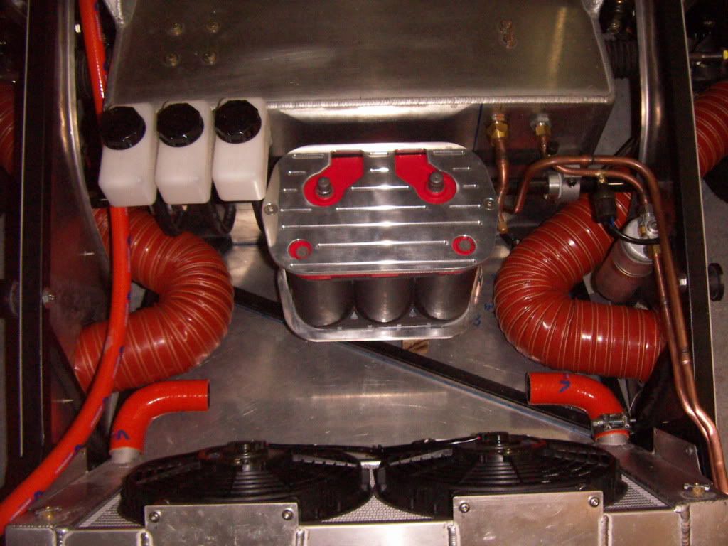
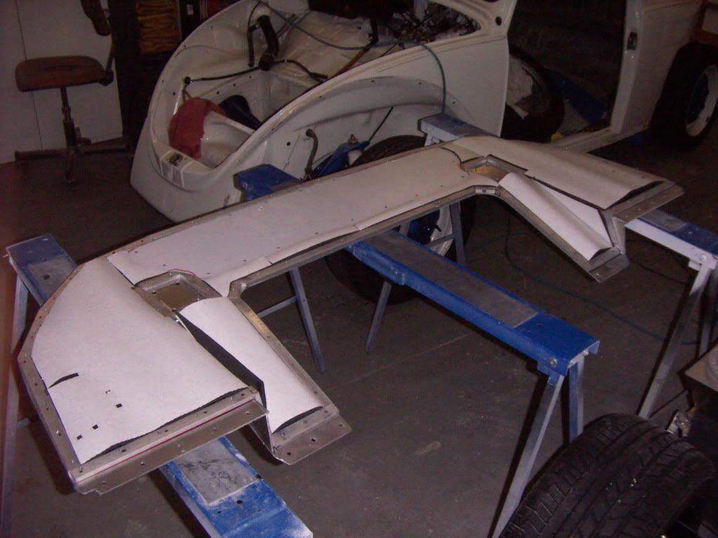
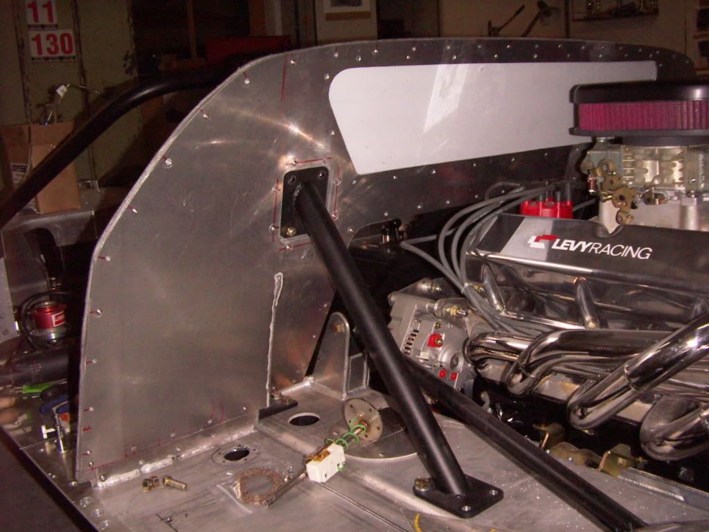
Welded Tab and installed fan
PICT3757.jpg

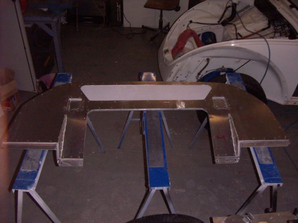
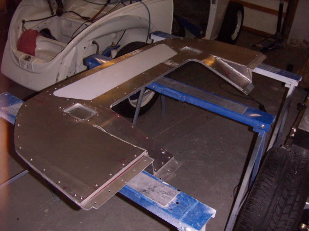
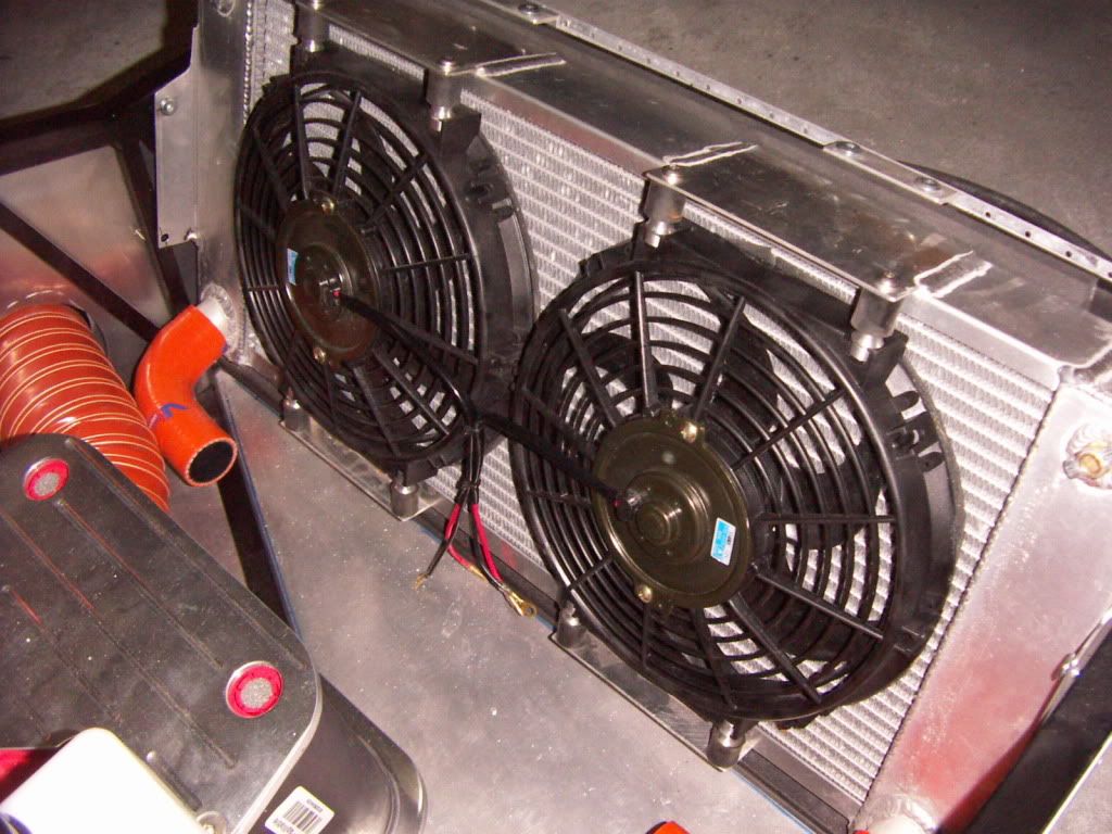
completely assembled
PICT3758-1.jpg


TOM

AWH : 568 h
 
Tom,

I need to get a pair of those "miniblinkers". I went to the link you posted and it's all in German. Do you know the brand name or where I could get a pair in the U.S.?

Thanks,
 
I just received an email from the company in Germany and they said they don't ship to the United States... rats!

Tom,

Could you order a set and ship them to Los Angeles? I would be happy to Paypal you the money.
 
Randy,
There should be plenty of motorcycle stores (sport bikes, not Harley shop) in the LA area that would carry these. Most run in the $17-$30 range for a pair. You have many choices of lens colors, shapes, LED/bulb, rubber/plastic arms. I have a set on my Buell X1 Lightning.
 
Randy,
Sorry for not reacting sooner, i haven´t checked my thread since a few weeks.

i will get a pair for you. I´m travelling to Detroit on 3rd of october and would take them with me and ship it from there, or you come and visit us at the RUN ´n GUN.

please pm me your postal adress.

TOM
 
AC PIPING

Hallo

Due to my front mounted battery i had to adapt the AC plumbing.

Hubert a mate of mine who´s daily job is with AC installations did supported me.
We redesigned the piping using copper tubes and brass fittings. We soldered them with silverlead.
PICT3761.jpg

We decided to install the trinary switch in a forward position for better cable routing. The original postioning is upwards. A downward position is not perceived as a "best practice" because the oil within the cooling-media will collect in the short pipe in front of the switch.
PICT3762.jpg

In order to clear the piping i changed the original triangle shape of the tow bar support into a "fourangle" shape.
PICT3763.jpg


The piping clears all other parts in the front compartment ( battery, brake ducting) and will be painted black.
PICT3764.jpg


PICT3765.jpg


TOM

awh: 575 h
 
ADJUSTABLE PEDALS

As my car will serve as democar, it has to fit different drivers. To do so i thought about a convinient solution for this task.

I came up with adjustable pedals. A standard car has fixed pedals and seats on adjustable tracks, i did it exactly the other way around. The seat is fixed but the pedals are on adjustable tracks.

I purchased a pair of standard raceseat tracks. To mount them on the RCR pedal box i welded iron angles in the lenght of the seat tracks to the sides of the pedal box. I than bolted the tracks on this angle stock. I than fabricated 4 iron angles to mount the seat track to the floor. The height was choosen in a way that the pedal box clears the carpet , which will be layed underneath later.
The seat tracks release mechanism was modified to accept a accelerator pull cable from my motorcycle inventory. The pull cable rund across the cylinders in their mounting holes.
A gas strut with 150 NM force and 5" travel is mounted on aluminium angles on the backside of the pedal box and the front firewall.

This is how it works.
sitting in the car one pulls the release cable and the pedal box is forced by the gas strut towards the driver in a smooth moving action. Now just push on the brake pedal and let the pull cable loose in the desired pedal position and the tracks release mechanism will fix it there.

The only thing left to do now is to fabricate a nice release lever which will be positioned on the floor in front of the gear lever and so is reachable very comfortable. After prooving the function today i will also make everything nice and square and repaint the whole thing black.

Seattracks mounted on pedal box
PICT3794.jpg


from the rear with mounted gas strut and release cable mechanism
PICT3795.jpg


release cable mechanism
PICT3796.jpg


mounted in the car
PICT3797.jpg


rear mount with gas strut
PICT3798.jpg


TOM

awh:590h
 

Randy V

Moderator-Admin
Staff member
Admin
Lifetime Supporter
Now that is a very slick pedal setup!!!!

I really like what you did with the throttle pedal as well...
 
Hello Tom

I am a "lurker" who has been watching your build log with keen interest. One of the reasons is that my car, on the road and finished - as much as any GT 40 - is finished has the 15 " Pirelli 345/225 tyre set up I believe you have. I am very keen to see some side views of your car but can' t view your pics- maybe a firewall problem on my side or because I'm technically challenged. Do you have pics posted anywhere else?
 
Last edited:
Hello Tom

I am a "lurker" who has been watching your build log with keen interest. One of the reasons is that my car, on the road and finished - as much as any GT 40 - is finished has the 15 " Pirelli 345/225 tyre set up I believe you have. I am very keen to see some side views of your car but can' t view your pics- maybe a firewall problem on my side or because I'm technically challenged. Do you have pics posted anywhere else?

This may help you.

Pictures by schwabtom - Photobucket
 
Hi Tom

I've just been reading through your build log and just wanted to say well done on your build so far. The car looks stunning and your a real inspiration to others like myself who are about to undertake a GT40 build.

Loving the colour too, although I don't know if anyone has pointed out that its looking rather similar to the mirage 720

1AvroMirage720FordGTF34.jpg


Keep up the good work

Trev
 
HI Rob

When i was just doing my motorbikes, i still had the argument that the horses are more expensive than the bikes, but now :--)))

See the excel sheet attached. This is my gearing. And if you need help with rear fender flares than just pm.

TOM
 

Attachments

  • GearSpeedCalculatorG5005.xls
    52.5 KB · Views: 275
DOUBLE LAYER FIREWALL

I want to have the nice and clean aluminium look of the original RCR firewall when i look at it from both sides, but i also want to have it insulated against noise and heat. Another target was to have no bolts and nuts from mounting components to it, sticking through the firewall and being visible from the passengers side.
The solution to it was to manufacture a second firewall bolted to the original one.
I started out with 8mm thick aluminium stock which i glued around the perimeter of the RCR firewall

PICT3799.jpg


I than duplicated the RCR design in 2mm thick aluminium which i attached to the firewall with the means of special bolts, which look like rivets, if you view it from 1m away.
PICT3802.jpg

special bolts ( don´t know the english expression for them, in german it is " Hülsenmutter")
PICT3815.jpg


After finishing this ( a lot of drilling i can tell you). I put a layer of DYNAMATE EXTREM for sound proofing towards the drivers compartment side of the firewall.
You also can see that the firewall window is mounted in between the two layers. There will be rubber gaskets on both sides of the window at the final installation.
PICT3804.jpg

After this i covered it with a layer of DYNALINER for thermal insulation. This is layed in a direction that it will glue to the "coverwall" to minimize resonance sounds there as well.
The total thickness of both layers is 8,2 mm and so slightly thicker than the distance between the two layers, resulting in a litte sqeeze and thus also minimizing the risk of vibrating sounds.
PICT3805.jpg

the finished product after attaching the "coverwall" ( not all bolts in it right now for mock up).
PICT3806.jpg

PICT3809.jpg


The complete firewall installed in the car. The components which attach to the firewall ( Ignition box, fuellines, header tank) will be bolted on with the means of nutrivets inserted in the coverwall.
PICT3810.jpg

recess for the rollcage support
PICT3811.jpg


The now app 14 mm wide firewall rim provides a perfect base for a thick rubberfoam gasket to seal against the spider.

the center panel will be done the same way.
TOM

Awh: 612 h
 
Last edited:
Status
Not open for further replies.
Back
Top