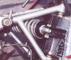
What would you do?

Ian Anderson

Lifetime Supporter
How about cutting both arm off at the Urethane bushes.

Cut each arm down by the desired amount (Same on each arm if my geometry is gorrect)

Reweld onto the bushes

But the arms will attach closer to the inner ends of the bushes but allow movement at the other end of the arm for lock nuts etc.

In effect it is what Frank is saying ane remaking the arm

Ian
 
Lynn,

Using Randy's dwg as a guide, carefully cut thru the outer tube wall only with a cut-off disc at the weld of the threaded bush to tube & at the red line point about 3/8" in from the first cut, now cut/split/remove that ring to allow the threaded bush to be pressed further into the main front tube leg & rewelded as per Randys dwg. Check with a probe to ensure that enough counterbore if any is present to allow the bush to do this, if not remove the bush with either a slide hammer on a 3/4" bolt or slide a length of round bar into the tube and screw the 3/4" bolt against it . This will create enough room for the locknut plus a bit more camber adjustment if reqd.

(( The material could also be removed in a large lathe if you have access to one that is capable of accomodating the inner urethane bush behind the three jaw's of the chuck & swinging the other leg over the bed, place the live center in the threaded bush while removing the 'ring &weld' area.))

Before refit use this A-arm to fabricate a simple jig for future mods or fabrication of new arms.

Jac Mac
 

Lynn Larsen

Lynn Larsen
Thanks all for the great suggestions. A lathe would certainly help insure a square cut Jac Mac (probably the most critical part of the mod after the acutal welding.)

Randy, there are rosette welds now that will have to be drilled out. I left them out of the drawing for simplicty.

Regards,
Lynn
 

Chris Duncan

Supporter
cut and re-weld at the inner ends. For best job replace short tubes that hold urethane bushes. Jig/clamp all pieces securely while welding and until fully cooled to avoid warp. Expect possible warpage even then depending on the type of weld. Tweak to align with careful heat (below weld temp).

there's going to be more chance of warpage if you re-weld the outer end.

if you go with rod ends on the inside you'll have to re-design the arm as they need to be perpendicular to mount plane (parallel to each other)
 

Russ Noble

GT40s Supporter
Lifetime Supporter
there's going to be more chance of warpage if you re-weld the outer end.

Sorry Kalun, I can't agree with that.

When the tube is shortened the weld will be on the END of the tube, not the junction. No warpage at all I would think, even with the rosette.

Cheers
 

Pete

Lifetime Supporter
Hello Lynn,

At least for the short term I would suggest drilling and tapping for one or more set screws.

Pete
 

Howard Jones

Supporter
Here's a radical idea. What if you bent the two long arms of the "A" at the same angle outwards. It would take the correct tubing bender and some setup but it would move the rod end inward towards the center-line on the car. Each straight leg would become a "s" so to speak.

A very slight bend outwards at the center of both tubes would get you the 3/8" you need.

No need to weld or reduce the strength of the piece.

Otherwise its a do over or replace the bushes with rod ends.
 

Chris Duncan

Supporter
No warpage at all I would think...
Cheers

Depending how close the arm coming in the side is to the end, there's not much room to chop off the end at the rod end. If it has to be cut off and moved down, then some chance for warp. Surely if the gusset is added there will be warp. It will suck the bush ends together when it cools, even if clamped.

Also depends on type of weld and welder's skill.
 

Russ Noble

GT40s Supporter
Lifetime Supporter
Yes Kalun, I agree that would be true if a gusset was added.

IMHO there should be no need, as the end is only going to be shortened 10 - 12 mm. Looking at Lynns diagram, it is going to involve cutting into the other arm by only a few mm. Because of the angle of the arms there is going to still be a lot more weld area on the junction than on the actual bush. The major loads going through this arm will be braking loads but most of those go through the bottom arm anyway.

Talking about weld area, all the braking loads in my top arm go through an 8mm bolt in double shear in an 11mm tube welded into the end of a 19 mm OD arm 1.6 wall thickness. The other end is just a normal sleeve insert in the 19mm tube with a .375" heim joint. And the braking loads will be generated by fairly sticky non DOT 10" tyres. Lynns stuff is way larger than this and is likely to be transferring much lighter loads as well.

I'd post a photo but my computer won't recognise my camera just at present :mad:

I'm all for the simple cure, anything more than that and I would just remake both arms to a better more easily adjusted design.

Pity Lynn didn't post pics so we could actually see what's involved.

Cheers,
 
Last edited:
:eek: No jam nut??? :eek:

Holy cow, do whatever you have to do so that a jam nut fits - jam nuts are a MUST! An absolute MUST! NOT LOCTITE!!!! In fact, you should be assembling the rod ends with an anti-sieze, not loctite.

This should all have been calculated into the design of the suspension; if not, send them back and insist on new ones that work - let them do the work they should have done the first time. A properly designed suspension should be able to have a nonadjustable ball joint and one adjustable one and still have enough range for adjustment UNLESS the frame is tweaked. How long has this situation existed? If this used to not be an issue and now it is, most likely your frame is tweaked (or upright - but that's a big tweak).

If it comes down to modifying the A-arms to work properly, the only answer is to shorten the A-arm so that a jam nut fits AND leaves a little more adjustment range (typically 3 or 4 threads on most cars, I don't see why a GT-40 would be any different.) I only skimmed through the other posts, but it looked like there were several variations of accomplishing that. I wouldn't bend the legs of the A-arms to do it though, you are just introducing buckling by doing that.

Whatever you do, get a jam nut on there. It's not a matter of taking out thread tolerances, it's a matter of tightening up the joint so the rod end doesn't:

1) egg the hole and make it worse
2) give you dynamically unstable geometry
3) weaken the rod end

A properly torqued fastener aids in prolonging the life of a fastener in dynamic loading. I know none of us actually torque jam nuts, but they ARE tightened and enough to a degree that will help. You will NEVER see a professional car without jam nuts. NEVER. If you do, they are not the front runners.

Sorry if this all sounds harsh, but I have no time to go back and "soften" it. Jam nuts are a MUST; there is no other way about it.

Either way, good luck with your car - you're a lot farther along than I am in terms of a beautiful sports car....
 

Lynn Larsen

Lynn Larsen
I've asked my wife to bring the digital camera home tonight, so hopefully I'll get some photos uploaded.

If I decide to make new A arms, I may just weld the rod end in place for the time being. I'll just have to get the new arms made before I can adjust the front end again. I had planned on getting a new threaded tube end anyway, so at worst, I'll be out the price of heim joint. BTW, the welding will be done using TIG.

Regards,
Lynn
 

Lynn Larsen

Lynn Larsen
Here is a photo from earlier in the build, but I it is the best one that I have to show what is being discussed.

Regards,
Lynn
 

Attachments

  • FrontLeftAarms.jpg
    FrontLeftAarms.jpg
    304.8 KB · Views: 415

Russ Noble

GT40s Supporter
Lifetime Supporter
Well Lynn,

I think all the options have been covered, there's only one man that can make the final decision! Shouldn't cause sleepless nights ;)

Cheers
 
Lynn,
Those angles are too steep to use a rod end on the upper arm inboard ends as it is now. They would wear right out, IMHO.

I would cut off the upper ends, shorten them the appropriate amount, then weld straight tubes to the ends, and install 2 welded threaded ends and you would be all set.

Best,
S
 
Personally, I wouldn't weld the rod end. Not knowing the carbon content of the steel, I would be worried about making it too brittle. Chances are, it has plenty of carbon in it to do that. It looks like you have plenty of room to take some material off the end of the arm there. If you have to, grind away the weld holding that threaded sleeve on, pull the sleeve out, cut the tube short - as close as you can to the other tube (even make it flush with the edge of the other tube if you have to), then reinsert the sleeve and weld it (or braze it even.) It seems like that should give you all the threads you need...
 
Lynn,
Go to Tornado Sports Cars and look at "TS40 Chassis". There you will see Andy's two styles of front suspension, fully rose jointed and poly bushed. I'm suggesting that you modify your upper and lower arms to mimmick his rose jointed arms.
Hope that clears up my post.
Best,
S
 

Howard Jones

Supporter
Now that I see a picture, forget the bend thing. I agree with Scott above. Not only will it work but it will preserve the strenght of the part. Cut off the end of the longest arm, remove the bung and weld in a new bung.

Or make new ones. At least you have an example of one and it's dimentions.
 
lynn, i just went and checked mine (pass side) and it appears to be at 0 degs (no alignment yet) with lock bolt on and 3 threads left. dont know what is different but i would say about 1/2 inch worth. let me know if you want to try and find it.
 

Ian Anderson

Lifetime Supporter
Lynn

The grey cells may be slowing up BUT did you not have someone back into your car when it was newly finished?

Did they perchance hit it hard enough to have twisted something? And now with this it is just confirming something is out of place?

Ian
 

Lynn Larsen

Lynn Larsen
John Ross,

If you wouldn't mind taking a quick measurement just to see if we are in the ball park, that might be helpful. Below is a picture of the arm with the measurment I took off of the leading edge at the middle of the arm. The outer corner of the bushing housing (chassis end) seemed to be the least ambiguous point to take the measurement from without removing the A arm from the car. On mine, a straight edge layed along the front of the arm is aligned with this point. The measurement from the flat face of the weld-in threaded tube end to the corner of the urethane bushing housing is eight and seven eighths (8 7/8) inches.

Ian,

The soccer mom incident happened after the alignment was done. Also, her trailer hitch only crunched the fiberglass of the nostril panel; luckily, there was no metal meeting metal at all. But, I am impressed with your memory :bow: Apparently you are not afflicted with CRS like I am :)

Regards,
Lynn
 

Attachments

  • FrntTLAarmDimed.jpg
    FrntTLAarmDimed.jpg
    20.4 KB · Views: 308
Back
Top