
You are using an out of date browser. It may not display this or other websites correctly.
You should upgrade or use an alternative browser.
You should upgrade or use an alternative browser.
Widebody RCR40
- Thread starter Adam H
- Start date
Can anyone advise whether any GT 40 Mk 1 s had their front arches flared? Mine ( which started life as a KVA) does and sometimes I feel guilty and am tempted to remove them. The flares I mean.
As I recall a number of years back, it was said that the Gulf Wide cars had different flairs over the front arches. There were photos on that thread, but I'm not able to immediately locate. My recollection was that you could only (barely) see them from top view..
As I recall a number of years back, it was said that the Gulf Wide cars had different flairs over the front arches. There were photos on that thread, but I'm not able to immediately locate. My recollection was that you could only (barely) see them from top view..
Yes, roughly 1" extensions over the top of the front wheel. A few pictures show that some of the flare extended down to the top of the rocker panel.
I've been working on the car but haven't had a chance to post.
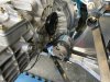
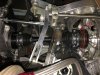
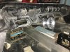
I thought I was going to be a pickle trying to fit a starter to the 930 box on a 8.2 deck SBF. The information out there shows a High Torque starter with a longer nose as the solution for the application. After talking to the fine people at High Torque they made me aware of a standard (not listed on site) starter that might work. The part number is IMI-101NL. I repositioned my engine/trans more forward. The total distance is 3.25 from the rear wishbone.
To my surprise the fit was excellent, even with the rear subframe I'm constructing. There also seems to be decent clearance for the axles.
I'm still waiting for those to verify final fit.
Attachments
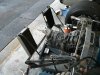
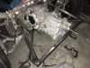
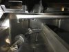
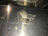
Started mocking up the shifter and realized the supplied 930 trans bracket wasn't going to work with my configuration. The engine is solid mounted so my attachment points can be on the chassis without any relative movement. I incorporated this into a 3rd (outboard) trans mount. There is getting to be a lot of junk out back with the coolers, oil filter, trans oil pump, thermostat...etc.
Attachments
Axle Drama
Some things worth noting after mocking up most of the rear end.
1. Foam mock up blocks are not the same (dimensionally) as the machined cast iron version. The angle of the rear mounting surface is off a couple 1/10ths of a degree and the bosses for the engine mounts are not the same.
2. RCR's (Drive Shaft Shop) axles are still MIA. I have been paid in full for 1 year and heckling RCR for 6 months. They just won't ship them. There is nothing with this kind of lead time...
I'm scared to send an engine to RCR for my (kit included) headers to be made.
Adam,
Rear frame looks good, and nice job on the rear trans mount as well. I had the same starter for a few years with the g50, but wound up paying a little more and getting the porsche part that is a little more robust. If you want to use the original style mounts for the rear clip/bobbins send me a pm. I made extra sets. Looks good, S
Rear frame looks good, and nice job on the rear trans mount as well. I had the same starter for a few years with the g50, but wound up paying a little more and getting the porsche part that is a little more robust. If you want to use the original style mounts for the rear clip/bobbins send me a pm. I made extra sets. Looks good, S
Scott
Lifetime Supporter
Adam, a few weeks ago the site went down due to spamming attack and they lost several days of posts after January 31st as outlined in the post below.
http://www.gt40s.com/forum/site-que...nts/49696-gt40s-site-issues-feb-2-2017-a.html
http://www.gt40s.com/forum/site-que...nts/49696-gt40s-site-issues-feb-2-2017-a.html
Adam, a few weeks ago the site went down due to spamming attack and they lost several days of posts after January 31st as outlined in the post below.
http://www.gt40s.com/forum/site-que...nts/49696-gt40s-site-issues-feb-2-2017-a.html
Ahhhh, that certainly explains it. Thanks.
Body alignment questions...
I've read everything there is relative to aligning the RCR40 body but need to know some other things before installing permanent attachments.
1. RCR and other people say to achieve 52-55mm (measured from the rear of the rocker to the chassis) as the reference for placement. I'd really have to hack the right side (lower front of panel) to move it back that far. Does that sound right?
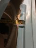
2. There is a flange on the upper rear of the spider that people claim mounts to the front face of the aluminum firewall (see image). If I force them to contact I can't get anywhere close to the 35mm spacing that RCR recommends from the spare tire lip to front of spider (see other image)
3. Most images of RCR40 rocker panels shows the front lip left intact while achieving good body alignment. I've had to cut the entire lip off to get them to move back. Is that normal?
4. If I can't get that 35mm spare tire pocket to spider distance will I have dash fitment issues?
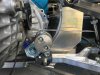
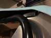
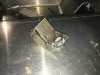
***Also, does the dust cap need to be removed from the Driveshaft Shop axles to fit into the trans output flange and/or wheel drive hub (see image). I didn't see anyone talking about this in their RCR/Porsche trans cars. It seems obvious that it does but I wanted to make sure.
I've read everything there is relative to aligning the RCR40 body but need to know some other things before installing permanent attachments.
1. RCR and other people say to achieve 52-55mm (measured from the rear of the rocker to the chassis) as the reference for placement. I'd really have to hack the right side (lower front of panel) to move it back that far. Does that sound right?
2. There is a flange on the upper rear of the spider that people claim mounts to the front face of the aluminum firewall (see image). If I force them to contact I can't get anywhere close to the 35mm spacing that RCR recommends from the spare tire lip to front of spider (see other image)
3. Most images of RCR40 rocker panels shows the front lip left intact while achieving good body alignment. I've had to cut the entire lip off to get them to move back. Is that normal?
4. If I can't get that 35mm spare tire pocket to spider distance will I have dash fitment issues?
***Also, does the dust cap need to be removed from the Driveshaft Shop axles to fit into the trans output flange and/or wheel drive hub (see image). I didn't see anyone talking about this in their RCR/Porsche trans cars. It seems obvious that it does but I wanted to make sure.
Attachments
Call me tomorrow and I'll talk you through it
My good friend Tom Schwab " eglitom"
Did the best forum write up on body fitting ever .
My good friend Tom Schwab " eglitom"
Did the best forum write up on body fitting ever .
So I think I have a body alignment plan thanks to some instruction from Fran.
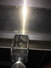
- The dash is still a bit of a mystery, at least the interface it ha with the front underside of the spider. With the dash seated flat (bottom the defrost vent resting on top of the chassis) the front tucks under the spider and forces it up. It creates quite a large gap between the bottom of the spider edge and the top of the chassis.
- Question- the steering column seems to zig/zag as it leaves the rack and goes through the heim joint and toward the dash drop and then driver. The pan under the dash has a hole for mounting the heim but it's not in line with everything else. Is the steering wheel supposed to angle toward the driver side window? Is this for an angled driving position or foot clearance relative to the pedals? I've marked the dash column center position as well as some other center positions on the chassis. They all line up (for the most part) with the rack input but the heim is about 1.5" to the right of that centerline.
Attachments
Chris Kouba
Supporter
Adam,
No, the steering wheel shouldn't angle anywhere you don't want it to. I ended up putting in the dash, seeing where the notch for the column was located, setting up the drivers seat, and then re-drilling a hole for the column to make sure the wheel was squared up where I wanted it. From the factory, the wheel/column does tilt one direction if you just use the factory hole.
Long story short, do what you need to make it work out the way you want it.
Chris
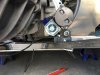
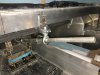
Worked through the steering geometry issues thanks to some very helpful advice from Tom. I didn't have the steering drop to work from (wasn't included with the parts in the kit) so I decided to go an alternative direction.
I wanted to stiffen up the area where the flat steel drop and spherical bearing are attached. Some people have used -2- sections of all thread to anchor the drop to the inner chassis pan. I wanted something more compact and with the ability to adjust steering column height a little easier.
I wanted to stiffen up the area where the flat steel drop and spherical bearing are attached. Some people have used -2- sections of all thread to anchor the drop to the inner chassis pan. I wanted something more compact and with the ability to adjust steering column height a little easier.
Attachments

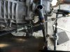
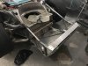
I've been making some steady progress. I decided some time ago, after seeing Tom's build, that I'd build an original style front and rear subframe. The front frame is considerable more complex than the rear. It's made from .065 wall 1.00, and .75 square tubing (for the most part). The front vertical section is .125 wall square and will be the attachment point for my Lemans jack points. The idea is to tie it into the .25" aluminum under pan and then build some sheet aluminum inner wheel liners.
I also wanted to make the front NACA ducts functional so I took another idea from Tom's build by using throttle bodies. I found some dodge/chrysler units that were roughly 2" OD and could be chopped up to act more like a vent valve than throttle body.
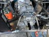
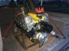
I also found an engine to use. Was something that turned up on Racing Junk and came from a failed project in my area. It's a Dart block 363 with Callies rotating assembly & CP pistons. Has Dart Pro 1 225 CNC heads. Unfortunately it was built for a turbo application so the pistons will need swapped.
I also wanted to make the front NACA ducts functional so I took another idea from Tom's build by using throttle bodies. I found some dodge/chrysler units that were roughly 2" OD and could be chopped up to act more like a vent valve than throttle body.
I also found an engine to use. Was something that turned up on Racing Junk and came from a failed project in my area. It's a Dart block 363 with Callies rotating assembly & CP pistons. Has Dart Pro 1 225 CNC heads. Unfortunately it was built for a turbo application so the pistons will need swapped.
Attachments
Similar threads
- Replies
- 4
- Views
- 916