Wiring fans to both come on for AC or Engine

Mark B.

Supporter
Tried searching the forum with no luck :(
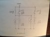
I'm wiring both fans to come on for AC and/or engine temp. I was just going to do this by running both powercell fan outputs to a single relay that in turn powers both fans. Is this a logical approach? Any better (more simple) options? Do I need to put diodes in the powercell outputs to prevent signal crossing?

Thanks!
 
I've not done with a power cell, but with a traditional harness, yes you need diodes, otherwise the temperature switch will engage your AC Clutch.
 
You don't need diodes to prevent backfeed with the Infinitybox system, though as Alan pointed out, it's a good strategy with a conventional harness.

The stock fans only draw 8 amps, IIRC, so you could actually run both outputs to the fans, which are wired in parallel. Use a 20 amp fuse in the Powercell.

Or run them through a relay, if you prefer, especially if you have upgraded the fans.
 
Mark

I took the same path being in Georgia with 100 degree days. I’m using the Infinity system and in discussions with Jay at Infinity, I sent my Master Cell back to them and they reprogrammed the cell. Took about a week turn time. Works as advertised. Stock fans for the time being. Summer is here so I will see how it works. I did build a shroud to support cooling.
 
Absolutely 100% use a relay. The wiring from infinity for the fans is insufficient and you will run the risk of melting your wires at best and melting your entire car at worst. This was one of my main issues with the infinity system; insufficient wire gauge. You should relay your fuel pumps as well if you are following their instructions. Fuses are not a replacement for relays.
 
Knowing this circuit is heavily used and wanting it right, and being a novice, I used a Ron Francis Fan Control Unit. It installed great, quality piece. You an set it up for one fan at one temp, second fan at another temp, with AC choices.
 

Howard Jones

Supporter
Here is a print. The 12v+ comes from what ever protected (fuse or circuit breaker) you prefer.

If either or both the water temp switch or the AC control switch is triggered then the relay(s) it controls will be picked and turn on the fan(s).

For some reason I have NEVER been able to understand why once in a while the picture resizer software I use flips things. Once it does you can never flip it back. But you get the idea. Sorry...................
 

Attachments

  • IMG_0517.JPG
    IMG_0517.JPG
    38.2 KB · Views: 408
Guys,

All of the POWERCELL outputs use 14-AWG wire with TXL insulation. Each of the POWERCELL outputs can carry up to 25-amps continuously.

We also pulse-width modulate the POWERCELL outputs for the cooling fans. This limits the inductive in-rush going to the fan motors to their steady-state values. There is a blog post on the Infinitybox website that goes through soft-starting in detail. Click on the magnifying glass in the upper right corner of the Infinitybox website and search soft start. You'll get all of the details there.

The largest cooling fans that you'd use in these cars would have steady-state current draws between 18 and 22-amps, well below the 25-amp threshold.

Most fans will tell you that you have to use 40-amp relays because they have no way to suppress the inductive in-rush of a motor. The relay has to be over sized to accommodate the in-rush. The POWERCELL output takes care of this.

Even if the POWERCELL output couldn't carry the current required to fan current, the output fuses would safely open to protect the wiring in the car.
 
I'm not an electrical engineer but I'll have to respectfully disagree with anyone who thinks it's good practice to run their fans without a relay. It's unsafe and frankly, for the little bit of work, pretty senseless to not run a relay for the added safety it adds.

Compare the 14AWG wire provided by the infinity system against the wire GM provides for the fan (hint, there's a big difference) and ask yourself if it makes sense to splice the two together - they're supposed to carry the same current right?

Similar story for the fuel pumps.

I'm sure Jay's done all the load calcs and has thoroughly tested his product.

However, I'm siding with:

- GM engineers; the crate engine wiring harness includes relays for both fans and fuel pumps, and use a heavier gauge wire
- every car I've ever worked on has used fan relays (granted, not many)
- every car my father in law has worked on has used fan relays (too many to count)

Last reason - [deleted] - I pinged said SLC owner and the electrical issue came down to improper wiring. It was my assumption that the system was setup per the Infinity recommendation but root cause is it wasn't properly fused.

Mark - ultimately it's your car so do what you think is right for you, but maybe head down to your local repair guru/shop and ask them what they think about not running a fan relay and see what their reaction is (be sure to include that you'll be running 14AWG wire).
 
Last edited:

Mark B.

Supporter
I didn't realize there would be so much passion around this topic :)
I really appreciate all of the input guys!
 

Howard Jones

Supporter
I looked for a simple calculator for wire size/current/wire length. Here you go. I do have a electrical engineering background and I don't see 14 awg working at 40 amps continuous current flow and still leave a safety margin.

I would size motor (fans, pumps, etc.) circuits at near their start up current draw because bearings get old, fans get stuck, loads to vary, etc. What you don't want is the wire getting overheated, especially if it is in a bundle or in a confined low air circulation space.

So........... 12AWG looks good for EACH fan with a common source lead sized at 10AWG. Use same sizes for grounds.

Protect at 1.33% of max normal current flow or in our case use 30 amp fuses for each fan or 60 amps for both. I don't like to common protect two or more loads so fuse each fan separately.

This will allow for a single fan to fail and the other to continue to function.

Automotive Wire & Wiring Guide from TESSCO - TESSCO.com

I won't get into the infinity box system with out a careful study of it. So I offer a straight forward old school B+, fuse, relay, load, sensor/switch option. I really can't see why not to do fan, pumps, lights, non electronic component, circuits this way.
 
Last edited:
Guys can anyone suggest a supplier for decent relays that handle 40 plus amps I have tried several Chinese favours and they all melt after a year or two .
 
it's fine to use the infinitybox to run fans as long as you're under the amp limit.

My sl-c has been using it for fans just fine since 2010

and it controls 4 fans on my 917
 
Here is a print. The 12v+ comes from what ever protected (fuse or circuit breaker) you prefer.

If either or both the water temp switch or the AC control switch is triggered then the relay(s) it controls will be picked and turn on the fan(s).

For some reason I have NEVER been able to understand why once in a while the picture resizer software I use flips things. Once it does you can never flip it back. But you get the idea. Sorry...................
I have the upgraded fans, so I have one AC output wire from the Infinity Box to trigger a relay that goes to one of the radiator fans. The other wire is the engine temperature output wire from Infinity Box that goes to a relay and goes to the other radiator fan. What I need is a diagram that will turn on both radiator fans when I turn on the AC and still let the other fan come on when the engine temp. goes up. Any help would be much appreciated.
 
Here is a print. The 12v+ comes from what ever protected (fuse or circuit breaker) you prefer.

If either or both the water temp switch or the AC control switch is triggered then the relay(s) it controls will be picked and turn on the fan(s).

For some reason I have NEVER been able to understand why once in a while the picture resizer software I use flips things. Once it does you can never flip it back. But you get the idea. Sorry...................
Is there anyone who could simplify/translate this diagram?
 

Bill Kearley

Supporter
To activate your rad fans for AC or water temp. Use of a relay is a must. To activate, have a switch to ground on the dash and use as a manual over ride. A grounding water temp switch at the thermostat. and for the AC your trinary switch will ground as ness. Wire so that any one of the three switches will provide a ground to activate the relay and power the fans. A good diagram is on the Vintage Air site.
 
Take the 2 output power wires for the fans in the Infinity Box and splice them together. Run 2 output wires from the splice. 1 wire to the trigger wire on a 30 amp relay and the other wire to the trigger wire on another 30 amp relay.
Run an in line fused power wire from the battery (or mega cell) to the input on each of the relays. (2 separate power lines)
Run a power wire to each of the fans from the power out put of the relays.
Ground the fan wires. Ground the relay negative wire.

When the Infinity system sends out power for a fan, either because of engine temps or ac on, it will trigger both relays which will turn on both fans.
 
Back
Top