Jimer's Build

Fans work at low road speed ...once above 30 mph the airflow is higher than a fan can provide..
If a shroud without the small pressure flaps is used the effective flow through the radiator is compromised and a less efficient cooling situation is created..

We tested many set ups like this during heat rejection tests during my days with OEM dyno/engine testing
 
Fran has commented that a shroud is not needed and as a matter of fact it can be less efficient. Thoughts?


I live in a small town with a very large community of classic/custom/street rod car builders. There seems to be an on-going “heated” (pun intended) conversation regarding shroud/no shroud. This is especially a sore subject among the purist restorers; they want a daily driver so they install an after market A/C unit but reject the idea of a shroud as a violation of originality. I don't get it, but anyhow, the consensus seems to be:
Whereas; a shroud may not be necessary in many/most regions of the country, we believe that we have a special set of circumstances! Our summer is about 7 months long with an average temp. of 107* and occasionally reaching highs of 125*. We use our cars as daily drivers, not trailer queens; therefore, understandably there is a large focus on cooling systems.


Right or wrong; I'm not sure, but personally, for low speed, around town driving; I'll feel better with a shroud.
Jim
 
Fans work at low road speed ...once above 30 mph the airflow is higher than a fan can provide..
If a shroud without the small pressure flaps is used the effective flow through the radiator is compromised and a less efficient cooling situation is created..

We tested many set ups like this during heat rejection tests during my days with OEM dyno/engine testing

Thanks Fran, that's what I was trying to say but you stated it perfectly; well stated :thumbsup:
Jim
 
are driving it on the street or strictly racing it? if its a street car you will want a shroud.


Grant, I totally agree; although I intend to occasionally track it my SL-C, it will be primarily a street car.

The reason I decided to go with a shroud is because I envision a lot of low speed around town driving. In my climate I believe a radiator shroud is a must!
Jim
 
Build Progress Week Ending 07/26/2013:
Once again lost some build time due to doctors appointments and parts snafus. So I decided to to do some designing and layout.
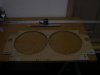
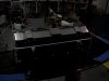

Radiator Shroud:
After over three hours of careful and exact “rechecking it four times measuring”, all I have to show for my efforts is cardboard template! (pic #001) Confident that my template was accurate, I took my template to a local metal shop, I had a very good one hour meeting with the owner.. I guess that I must still be living in the stone age. Silly me, I thought that they would simply lay my template on top of a hunk of 1/8” aluminum, trace it out and cut it. Bryan explained that is old school; today everything is done by computer and that is the reason he took his time, making sure that he understood each cut and its dimensions.


Once the dimensions are entered into the computer, a laser guide water jet will cut design. I'll have to sign off on a finished drawing and shroud should be complete in about two weeks.


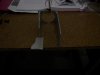
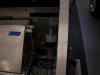
Pedal Assembly: (pic #003)
After several hours of dry fitting and repositioning the pedals, I just was not happy. I know that several builders position the plunger nob of the adjustable pedal slide in the front for ease of accessibility. The problem for me was that when I would transition my foot from the go pedal to the stop pedal, my foot would hit the nob.


I moved the nob to the rear and that solved that problem but now I discovered another problem. When I would transition my foot from the accelerator to the brake pedal, my size 9.5's would hit the bottom of the steering wheel “tilt” drive motor. Same problem with the clutch would hit the bottom of the steering wheel “telescopic” motor.


I removed the Tilton pedal assembly from the adjustable slide and adapter plate; this gave me an extra 13/16”. That helped a little but my foot still hit the bottom of the motors and I just was not comfortable with that!


I now made a couple of executive decisions! The first one was to scrap the idea of using the adjustable slide bracket; once again, if anyone is wanting one these...”such a deal I have for you”! The second decision was to put the installation of the pedal assembly on hold until I researched the steering column issue.


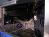
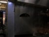
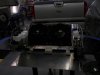
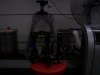
Steering Column Destruction: (pic #007)
I have to take this opportunity to say the I have read the build manual and each SL-C builders site several times and managed to pick up little tips from each. I don't know that I would be able to do this without all of the free flow-willing to help information on the SL-C Clubhouse Forum. But I have to give special acknowledgment and kudos to Zoe's blog! It seems like every problem that I encountered, Zoe has had and already successfully resolved! I'm trying to train myself to check on Zoe's blog before going onto the next project. The best advise I could offer an SL-C builder just getting started is.... read Zoe's blog!


The problem is: the steering wheel tilt motor (right side of column) and the telescopic motor (left side of column) are mounted vertically to a useless rectangular housing that surrounds the Cadillac steering column. We cut the housing off just forward of the two actual mounting points that hold the steering column to the ceiling of the drivers foot well of the chassis. I have to honestly confess, that had I not seen that Zoe had successfully performed this surgery, I don't think that I would have had enough nerve to butcher my brand new steering column!


Amputating the housing allowed us to fabricate and install a 3/16” aluminum plate to the to of the steering wheel mounting point and and mount the two motors horizontally.(pic 5 & 6) This afforded me another 4” inches of clearance between the bottom of each motor and my size 9.5's.


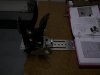
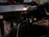
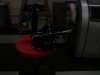
Installing Vintage Air Unit in Passenger Foot Well: (pic #004)
This was like the old saying of trying squeeze 100lbs. of (lets call it) “stuff” into a 1lbs. Bag! Once again Zoey to the rescue! There is absolutely no clearance between the right side of the V.A unit and and the 45* angle curb side of the passenger side foot well with the fittings installed and it is impossible to tighten the fittings after the unit is install. Solution...bend the right side copper tubing inward. This is another one of those things that I would be hesitant in doing if I had not seen that someone else had successfully accomplished the task without damaging the Vintage Air unit.


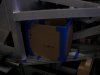
Now for a couple of tips of my own; there is 1/4-20 mounting bolt on the left front side of the the unit. It is impossible and unnecessary to use this mounting point, so remove the bolt. The 1/8” you gain by removing the bolt is the difference of getting the unit in or not! There is also a temp. nob and bracket on the right front; remove it and find a new place to mount it because it can't fit between the V.A and the center upright supports. I fabricated a “L” shaped mounting bracket for the right side front out of 1-1/4” perforated banding; securing one side to mounting point on the unit and the other to the ceiling of the passenger side foot well via a drilled & tapped 5/16” hole.


The two top rear mounting brackets have approx. an 2” slot so that they can be adjusted. I found it too difficult to feed a bolt down and try to tighten a nut blindly and to feed up through the bracket and the chassis ceiling without the bolt falling out was equally difficult. Solution: I fed a 5/16”X1” bolt up through the bracket, carefully measured the distance for my the center of my ceiling hole and the curb side wall of the chassis. I placed a 5/16” shoulder serrated lock nut on the up-ward bolt, turning into a fixed position stud and pushed through the ceiling of the chassis, affixing another shoulder serrated luck nut. Access can be had through the top inspection port hole.


This whole process only took almost an entire day and I'll have remove the unit to install my hoses but at least now I now know that you CAN put 100lbs of s_ _ _ into a 1lbs bag :thumbsup:


Jim
 

Attachments

  • SL-C Progress Week Ending 0-26-2013 001.jpg
    SL-C Progress Week Ending 0-26-2013 001.jpg
    107.4 KB · Views: 387
  • SL-C Progress Week Ending 0-26-2013 003.jpg
    SL-C Progress Week Ending 0-26-2013 003.jpg
    105 KB · Views: 397
  • SL-C Progress Week Ending 0-26-2013 007.jpg
    SL-C Progress Week Ending 0-26-2013 007.jpg
    90.9 KB · Views: 386
  • SL-C Progress Week Ending 0-26-2013 004.jpg
    SL-C Progress Week Ending 0-26-2013 004.jpg
    133.3 KB · Views: 392
  • SL-C Progress Week Ending 0-26-2013 005.jpg
    SL-C Progress Week Ending 0-26-2013 005.jpg
    114.7 KB · Views: 407
Last edited:
Build Progress-Week Ending 08/02/2013:
Friday, Aug 2nd. marked the one month anniversary of the delivery of my SL-C!


We managed to get a lot of small tasks accomplished.
I finally received my back ordered Spanner Wrench (KD Tool- Fastenal part # 0281903-$52.04) so we were able to tighten the lift kit keeper & jam nuts.


Mike tidied up/shortened the foot well brake line's. Looks good and my left foot no longer hits the brake line. He also torqued and marked some front end bolts.


Mike also cut down some upper “A” arm bolts and some 1/4-20 mounting bolts we had protruding through the monocock chassis. Rather than trying to stock all different lengths of bolts, I just bought a couple of boxes of long bolts and we cut off the excess as we go.


George and I fabricated and installed a 1/8” aluminum bulk head, isolating the gas tank from the engine compartment. We made an access door on the street side of the bulk head. This will allow me to access the fuel shut off and Facet Fuel Pump filter.(pic #002)


I dry fitted the fuel tank shut off valve, filter and Facet Dura-Lift Solid State Fuel Pump (FAC-40290-Pegasus Racing Supplies-$129.99) on the street side of the fuel tank. (pic #003)


I picked up the shop drawing for my radiator fan shroud, I “red lined” some changes and returned the drawing to the metal shop. I should have the completed shroud by early next week. Once we get the shroud mounted to the radiator nose piece, we'll be able to install the nose piece and forge ahead with some other items that have been on hold.


This doesn't sound like a lot and with the possible exception of the bulk head; certainly aren't items that looks like anything was actually done. However, these were all important items and very time consuming projects. Actually, we would have been able to accomplish much more, but we are at a parts and information impasse.


I'm leery about mounting anything in the engine compartment until I receive my side exhaust system. Not knowing exactly how this is going to mount, how much space it will take up or where it will come off the the exhaust manifold, is stopping me from making any progress in the engine compartment. Extremely frustrating!


As for the information impasse: We tried installing the the Tilton pedal assembly but am having a difficult time understanding how the GM throttle linkage adapts to the Tilton? I looked at several pictures on builders sites on the forum but it seems that everyone has a different approach and I'm trying to figure out which is the easiest and best. If anyone cares to chime in....your input will certainly be welcome!


Everyone, have a good week; I hope I'll be able to report better progress next week!
Jim (build #145)
 

Attachments

  • Week Ending 08-02-2013 002.jpg
    Week Ending 08-02-2013 002.jpg
    84.4 KB · Views: 296
Sorry, I forgot to post pic # 003, so here it is.
 

Attachments

  • Week Ending 08-02-2013 003.jpg
    Week Ending 08-02-2013 003.jpg
    97.6 KB · Views: 337
Build Progress-Week of 08/09/2013:
Mike is on vacation for a couple of weeks and George is tending to his wife, so in between my own doctors appointments, I've been plugging along by myself.


Before Mike left, he started to adapt the GM throttle linkage to the Tilton pedal assembly. I finished it up and installed it in the car. Thanks to the fellow builders who responded to my “Tilton Pedal Question” thread; the variation of different ideas allowed us to come up with a simple design that should work well. Because the mounting plate seemed a little flimsy with to much flex, we fabricated a 1/2”X2”stand-off support between the floor and the bottom of the mounting plate that eliminates all of the flex even with harsh throttle abuse! Pic #)9 & 010) The question I still have is how much “throw” you guys have to full throttle? I have only about 2-1/2” from full off to full throttle and compared all of my other cars; it just doesn't feel right!


I picked up my radiator shroud from the metal shop, so I got to play black smith and bend the 1/8” X5” mounting tabs into place. When I designed the shroud, I just could not get the bends on the template tight enough for my satisfaction so I decided to have the metal shop just leave six straight 5” tabs and I would custom bend them to fit. That worked out well! I affixed some rubber anti-vibration strips to eliminate any metal to metal and metal to plastic vibration rattles. I also installed some adhesive backed “open cell” A/C foam to form a n air tight seal. (pic #07 & 08)


I mocked up a battery box (pic # 06) but am reluctant to start fabricating it until I receive my exhaust system!
Jim (build #145)
 

Attachments

  • SL-C Build Week Ending 08-08-2013 007.jpg
    SL-C Build Week Ending 08-08-2013 007.jpg
    110.9 KB · Views: 362
  • SL-C Build Week Ending 08-08-2013 008.jpg
    SL-C Build Week Ending 08-08-2013 008.jpg
    87 KB · Views: 363
  • SL-C Build Week Ending 08-08-2013 009.jpg
    SL-C Build Week Ending 08-08-2013 009.jpg
    92 KB · Views: 350
  • SL-C Build Week Ending 08-08-2013 010.jpg
    SL-C Build Week Ending 08-08-2013 010.jpg
    76.9 KB · Views: 346
  • SL-C Build Week Ending 08-08-2013 006.jpg
    SL-C Build Week Ending 08-08-2013 006.jpg
    84.3 KB · Views: 313
Mine's about the same. Luckily it doesn't behave like an on-off switch - it works better than I anticipated.

"The question I still have is how much “throw” you guys have to full throttle? I have only about 2-1/2” from full off to full throttle and compared all of my other cars; it just doesn't feel right!"

Thanks Mike, that's good to know and makes me feel better.

Jim (build #145)
 
Thanks Mike, that's good to know and makes me feel better.

Jim (build #145)

Careful mounting of the ETC unit allows you to get the maximum travel from the pedals.

To do that, measure the max pedal travel without anything attached to it, then mount the ETC in such a way that you can get the max travel you need. I needed about a 4" extension to the ETC where it attached to the pedals.
 

Ken Roberts

Supporter
Jim you should decide where you are going to mount the hand brake lever in the not to distant future. If you decide to mount it on the left side of the driver than you will need to elevate the battery so the cables can run underneath. I have mounted my battery in the same location and made room for the cables to travel underneath. I can snap a picture for you if needed.
 
Careful mounting of the ETC unit allows you to get the maximum travel from the pedals.

To do that, measure the max pedal travel without anything attached to it, then mount the ETC in such a way that you can get the max travel you need. I needed about a 4" extension to the ETC where it attached to the pedals.

Thanks Will, I'll give that a try.

Jim you should decide where you are going to mount the hand brake lever in the not to distant future. If you decide to mount it on the left side of the driver than you will need to elevate the battery so the cables can run underneath. I have mounted my battery in the same location and made room for the cables to travel underneath. I can snap a picture for you if needed.

Ken, I'm going to install my hand brake on the left side. Your heads-up timing is perfect, because that's one of the things I plan on tackling this week. If you wouldn't mind, I think a picture may be very helpful.

Thanks again,
Jim (build #145)
 

Ken Roberts

Supporter
Here's a picture to show how I elevated the battery with some rectangular aluminum tubing to allow a path for the handbrake cables. A C6 Corvette plastic battery tray was modified to hold the battery down. The tray is riveted to a sheet of aluminum. I chose a C6 Corvette battery group size (85).
 

Michael Fling

Supporter
Jim,
Your build is coming along beautifully! Question. Do you intend on putting on a transmission and oil cooler? If so, could you share your choices. Thanks.
 
Thanks Ken, I like the idea of running the cable through the tubing. My still unknown is where my side exhaust is going to go.
Jim
 
Thank you Michael, I don't know about beautifully but sooner or later I'll get there!

No, I never intended on using a trans cooler and I plan on seeing what kind of oil temps I generate before I decide on a oil cooler. One of the reasons I decided to go with the side exhaust is to eliminate running hot exhaust over the trans. Is that the main reason for high exhaust temps...NO! But it certainly doesn't help. I guess I'll find out
Jim (build #145)
 
Back
Top