Norfolk Tornado

Hi Jason,

I know what you mean, with ‘measure twice, cut once’. With me it’s that mantra and parts are mocked-up and go through a few iterations until its good enough
Let me know when you back in Norfolk next, as you more than welcome to come & have a proper a look
Regards,
Andy
 
Hi Jason,

I know what you mean, with ‘measure twice, cut once’. With me it’s that mantra and parts are mocked-up and go through a few iterations until its good enough
Let me know when you back in Norfolk next, as you more than welcome to come & have a proper a look
Regards,
Andy


thanks Andy - I may be over in August some time, I'll let you know once plans are made.
Cheers,
Jason
 
Not a lot to show at present. I spent most of the bank holiday lying under the car installing the feed & return lines to the tanks and connecting up the 3-way Pollack valve. The system has been done in 10mm copper tube and adapters soldered in where the pipe needs to be reduced to 8mm when they need to go to a matching fitting. All the pipe ends have an olive soldered onto to ensure there is no chance ot the pipe coming off. It makes assembly more difficult, but it’s the right way to do it. It’s a bit tight with the low pressure pump mounted and the gear shift coupling in the same space, but it does all fit - just :thumbsup:

I did however get the aeroquip lines finished, as these will all that will be visible when it’s all finished

Regards
Andy
 

Attachments

  • P5021652.jpg
    P5021652.jpg
    202.2 KB · Views: 756
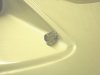
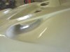
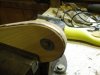
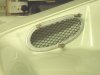
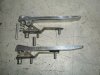
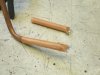
Whilst I’m working my way through all the electrical requirements, I’ve also been working on door handles & locks. The handles & mouldings were provided by Darren at GTS and I fabricated the mounting brackets. This method of mounting results in no mounting holes the horizontal surface which would lead to water entering the door and setting the handle to the edge of the door can easily be achieved with spacers behind the mounting bracket.

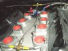
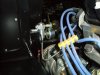
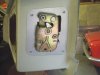
The door locks are new old stock parts left over from a previous Ginetta project (another UK parts bin special, which uses MG Midget door latches). New latch pins have been made, as I considered the original matching latch plate too bulky for its new application

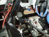
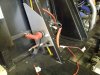
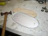
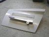
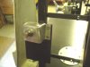
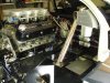
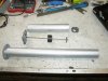
To get the lock in the correct place relative to the external handle, I made a temporary mounting plate out of 1mm ally sheet (see photo), so I could easily adjust the final position. Once the final position was established a 3mm ally mounting was made. The new mouldings have yet to be glassed in, but having full access on the inside of the door has made the installation of the locks a great deal easier
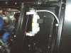
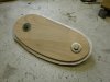
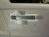
The latch pin mounting plate, which is made from 3mm aluminium, has been left open at the bottom, so that I can access the locking nut

I’ve still to finish polishing the handles and radiusing the edges, with the final finish being either clear powder coat or anodise. Slowly getting there…….

Regards
Andy
 

Attachments

  • P1.jpg
    P1.jpg
    117.2 KB · Views: 745
  • P2.jpg
    P2.jpg
    118.5 KB · Views: 719
  • P3.jpg
    P3.jpg
    209.3 KB · Views: 756
  • P4.jpg
    P4.jpg
    146.4 KB · Views: 728
  • P6061662.jpg
    P6061662.jpg
    141.5 KB · Views: 733
Hi Andy,

Good skills, door bits look ace.

I got my prototype seat back from the trimmers today. It's your seat shell design trimmed with Alcantara centre and leather look vinyl sides. I'm really pleased with how it's come out.

How are you getting on with yours?
 

Attachments

  • gts40-seat2.jpg
    gts40-seat2.jpg
    136.4 KB · Views: 706
Hi Darren,
your seat looks really good. My seats are at the back of the workshop waiting for me to take the to be trimmed. I keep getting side-tracked with everthing else on the car that needs doing!

Regards,
Andy
 
G'day Andy,

Waaaay back you mention that the bellhousing was sourced from Chris Cole. You appear to have an inverted UN1, and I can do without the hassle of inventing something similar.

Do you have a contact for these bellhousings/Chris Cole?

Many thanks,

Clive
 
Hi Clive,
My UN1 has not been inverted, the engine/trans has just been dropped in the chassis. Sorry, can't really help on inverting one of these boxes.
Regards
Andy
 
Andy,
The swirl pot looks in the pic like it is colse to the No.1 exhaust port. Might pick up a little too much heat in that location unless it is just the pic itself. If it isn't, you might want to consider a shield around that side of the pot.

Bill
 
Hi Bill,
the photo I uploaded is a bit deceptive as the swirl pot is up against the bulkhead 4-5" away from No1 header. The attached is a little clearer. I'm still concerned about heat build up in the pot, but will measure the temp & take appropiate actions when its running

Regards
Andy
 

Attachments

  • P5021653.jpg
    P5021653.jpg
    225.2 KB · Views: 711
Small fiddly bits have included pre-filters & fuel level sensors. Although I’ve got an almighty filter before the high pressure pump and the low pressure pump incorporates a pre-filter, I was concerned about picking up debris from the bottom of the tanks and then jamming/blocking the switching valve, so some sort of pre-filter was ideally required.

I’d deliberately used copper tubing for the pick-up pipes, as it is easy to bend and importantly solder and I sourced some very fine copper woven mesh with only a .014” opening. This would then stop any swarf getting into the system. This was then soldered onto the pick-up pipe to give a ‘fit & forget’ solution

I’d heard previously that it is feasible to match a VDO dip-tube sensor to Smiths fuel gauge. These VDO sensors are available in various lengths and are less prone to fuel surge problems like the more conventional swing arm sensor. I sourced a pair of oversize units, which were then cut down to fit my tanks. By working out the resistance required to drive a Smiths gauge from full to empty, I was able to change the resistance in the sensor accordingly.

Although not very linear around the mid point, it does show full & empty accurately and bearing in mind, the tank is not a linear cross section, it will do what I need.

Regards
Andy
 

Attachments

  • Fuel strainer.jpg
    Fuel strainer.jpg
    152.4 KB · Views: 510
  • VDO sensor.jpg
    VDO sensor.jpg
    235.4 KB · Views: 545
Andy,
Those fuel sensors are hands down the way to go. My only siggestion is to add a trap door setup at the ful pickup to insure fuel pickup when braking. Include the fuel return to that area to help out as well. Having hot fuel returniong to the pumps is not a problem. Heating the fuel up is helping the atomization process carb or FI. Since you are pretty good with electrics, consider adding a low level lite for alerting you that the tanks are less than 1/4 full. My setup(sender) came that way and I feel it is a necessity with the way these cars can consume the petrol.
With your revised pic, I will be surprised if you don't have to add a shield in front of the swirl pot. I have seen my exhaust pipes with the rpms lust under 2000 and they are starting to glow. You might want to consider adding a set of small compartment fans in the corners of the engine bay to help aleviate the heat. They can be set up with off delay timers from Waytec. Mine don't turn off for 3 minutes after shut down. The fiberglass can become very soft where they come near. Should be on my bulid site(DRB #5) on page 5 post 92. It will make a big difference on those hot days and keep the cabin a little cooler.Set them to come on with a thermostat.
Keep up the good work.

Bill
 
Progress on the ’40 recently has slowed, as I’ve been distracted with family, work and garden stuff, as well as sorting a car out for my son, now he’s passed his test. It’s got the classic 1275cc ‘A’ series engine producing a whopping 50hp and is the last of the carburetted engines, but it still has a catalyst which is a bit strange. Although difficult to tell from the photo, it’s got a silver union jack on the roof, which is effectively the inverse colours of the car next to it, which is my wife’s.

I’d also forgotten how small it is (i.e no room to get your hand in or accessibility to bolts etc) everything is on a Mini and there’s only one thing worse that bodged electrics and that’s Lucas bodged electrics!

Regards
Andy
 

Attachments

  • P7261670a.jpg
    P7261670a.jpg
    347 KB · Views: 469
Back to the ’40, I don’t seem to be making much visible progress on it recently, however a few areas progressed
  • Electrical system
    • Rear fuse/relay box sourced & mounted
    • Inertia switch fitted
    • Rear lights fitted
    • Front lights (not yet finished)
    • Smiths gauges on order
  • New front clam pivot hinge
  • Driveshafts sourced
  • Centre-lock wheel nuts designed & sent for manufacture (For the IVA)
  • Rear deck repaired (where the Rover plenum originally protruded through) & the air snorkels bonded in (a sod of a job)
The micro LED front indicators I used (Ebay or CBS & thanks Brett for the tip-off) will fit under the eventual lens covers, whilst still meeting the 45 degree angle of visibility for the IVA.

I’ve added a permanent bleed from the radiator to the expansion tank using a dia 6mm high temperature nylon pipe, which runs inside the N/S chassis rail. Where it goes through the bulkhead into the engine bay, it changes to -3 Aeroquip to give it more protection.

As I’m designing a custom wiring harness which includes the AC, engine management system, electric power steering, this is taking a lot of planning and all the parts (switches, sensors etc) have to be located on the car, so the harness made to fit. A simple 1-wire layout harness is being laid in the car to enable the proper harness to then be made & tested off the car on a build board – Well that’s the theory, we’ll see what actually happens!

Regards
Andy
 

Attachments

  • P8181676.jpg
    P8181676.jpg
    115 KB · Views: 560
  • P8181677.jpg
    P8181677.jpg
    237.7 KB · Views: 624
  • P8181678.jpg
    P8181678.jpg
    202 KB · Views: 595
  • P8181680.jpg
    P8181680.jpg
    215.7 KB · Views: 558
  • P8181687.jpg
    P8181687.jpg
    88.5 KB · Views: 576
  • P8191695.jpg
    P8191695.jpg
    204.9 KB · Views: 597
  • P8201706.jpg
    P8201706.jpg
    205.1 KB · Views: 527
Andy,
Your Inertia switch looks a little inaccesable where you have it mounted. Will it eventually be in the cabin? Sometimes it doesen't take much to trip it.

Bill
 
Andy buddy - I keep telling you. Stop saying stuff like that.. people will start to belive I research this stuff and know what I am going on about.... Its all smoke and mirrors I tell you ;) LOL

Looks awesome work as always my friend
 
Hi Bill,
The inertia switch is accessable from the engine bay and I used this type before and they do need a good jolt to set them off
Regards,
Andy
 
Unfortunately with the ’40 I easily get distracted whilst I’m supposed be concentrating on getting it through its IVA! I also seem to get a great deal of satisfaction/frustration in taking a piece of metal, cutting & shaping it, until it’s just too small and then starting again!
Even though I plan to run with foam filters, I like the idea of stone guards protecting the air inlets, which I’ve seen them fitted on some the original road cars
To cover the edge of the mesh, I made a simple hammer form to the required shape from some scrap laminate flooring. By pre-trimming the aluminium close to the desired length, it was easy to get it to shrink round corners and give a snug fit to the former. The middle was then roughed out with a jisaw and finished with a bobbin sander. The finished parts will eventually be powder-coated & screwed into place

A bit of work on the dashboard, with instrument holes cut & aluminium removable switch panels made. The lower panel on the LH side is to take the heater fan & AC controls. These will eventually be powder-coated black with white lettering. As used on some of the original road cars I’m using a Mini switch stalk for the indicators, main/dip beam & horn. A ‘Bright 6’ LED module is used for most of the warning lights, with the remainder being the traditional ½” Lucas lights. The switches can’t be laid in until I get the correct steering wheel to define where the IVA defined out edge plus 5” on the LHS of the wheel.
Regards,
Andy
 

Attachments

  • P8271713a.jpg
    P8271713a.jpg
    167.2 KB · Views: 484
  • P8271714a.jpg
    P8271714a.jpg
    145.8 KB · Views: 520
  • P8271717a.jpg
    P8271717a.jpg
    191.4 KB · Views: 522
  • P8271718a.jpg
    P8271718a.jpg
    116.6 KB · Views: 545
  • P8201702a.jpg
    P8201702a.jpg
    177.1 KB · Views: 586
  • P9041678a.jpg
    P9041678a.jpg
    123.1 KB · Views: 590
Back
Top