
You are using an out of date browser. It may not display this or other websites correctly.
You should upgrade or use an alternative browser.
You should upgrade or use an alternative browser.
Norfolk Tornado
- Thread starter saxoncross
- Start date
Got some time in the w/shop over Easter, well the weather was crap and my wife was working, so what else!
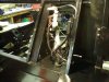
Engine harness is finished. It’s covered in Raychem heat-shrink, which is good for temperatures up to 150°C and has a good oil & fuel resistant finish.
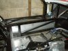
The main vehicle harness now been also been fitted, I’ve still got to terminate it around the rear end, but it did eventually go down the central tunnel. For all the effort that’s gone into this, there’s not a lot for it to show, but there again that’s the whole point of a good installation.
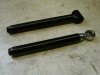
After discussions with John Christian about the use of Poly-bushes I also re-did the inner rear suspension, with a L/H rod end for the upper link and a new lower inner bush. See separate write-up under Chassis & Brakes;
http://www.gt40s.com/forum/gt40-tec...shes-tornado-gt-forte-gtd-etc.html#post367899
Regards
Andy
Engine harness is finished. It’s covered in Raychem heat-shrink, which is good for temperatures up to 150°C and has a good oil & fuel resistant finish.
The main vehicle harness now been also been fitted, I’ve still got to terminate it around the rear end, but it did eventually go down the central tunnel. For all the effort that’s gone into this, there’s not a lot for it to show, but there again that’s the whole point of a good installation.
After discussions with John Christian about the use of Poly-bushes I also re-did the inner rear suspension, with a L/H rod end for the upper link and a new lower inner bush. See separate write-up under Chassis & Brakes;
http://www.gt40s.com/forum/gt40-tec...shes-tornado-gt-forte-gtd-etc.html#post367899
Regards
Andy
Attachments
Prior to terminating the rear fusebox & ECU, I’d realised that the panelling in this area has to be finalised and the ideally the fuel tanks needed to be installed at the same time.
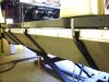
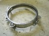
As my tanks use 3 straps to secure them (I don’t like the idea of a bolted design which could lead to fatigue failures/leaks) I wanted a simple solution to tighten the straps without resorting to a complicated turnbuckle arrangement. Eventually came up with the idea of using jubilee clips, which are split & then riveted to the straps & chassis. This allows easy strap tension adjustments and no need to drill out any rivets if I want to remove them at a later date.
The tanks are sitting on 10mm closed cell foam and to stop any fretting, the straps are covered in rubber tubing (old bicycle inner tubes!). I’ve also added a rear tank vent, but I’m still not convinced I need it, but it’s easier to get the boss welded into the tank before any fuel goes in. This connects up with the front vent which goes to the roll-over valve. The top & side of the tanks are covered with a light foam, with the aim to absorb any noise from the fuel moving around, although I don’t suppose I’ll hear it over the top of the engine!
I’ve also made the door pocket closure plates. As I’m not using a separate strap to pull the door closed, the top edge needed to be stiffened, which was done with top edge being rolled around a 5mm aluminium rod. This also gives a nice tactile edge to pull against. This took a bit of fiddling, but I’m pleased with the result. I think I could have got in a few more lightening holes in the panels, but as my wife said, more holes for stuff to fail out of! The door pockets will eventually be flocked in black nylon and the aluminium with either be left natural or covered in the carbon wrap to match the dash switch panels.
Regards
Andy
Attachments
With all the recent rain in the UK, I’ve been slowly progressing the ‘40
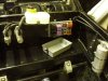
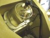
With both tanks now installed I finished the plumbing on the LP pump & tank switching valve Although this was done before final top plate finally riveted on, all clips & nuts etc are easily assessable from below or the side.
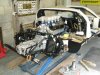
Whilst the rear suspension was off, and the engine out, I took the time to repaint the rear half of the chassis prior to final assembly. I was never particularly happy with the finish when it was all painted a few years ago and it’s taken a lot of knocks during the build process and seem to be very prone to chipping even though is was supposed to be special ‘chassis paint
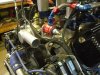
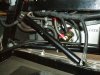
The rear fuse/relay panel and ECU has been terminated and the engine in stalled hopefully for the last time. Diagnostics connector is easily accessible from the passenger side. All the lower passenger compartment panels have been finally fitted. These have gathering dust for the last 4 years since I made them, so it’s nice to finally clear some space and see it finally going together!
The rear suspension is fitted and set at nominal conditions. The drive-shafts are custom units I had made with Renault inners and Ford outers, therefore removing the need for the inboard adapters.
Regards
Andy
With both tanks now installed I finished the plumbing on the LP pump & tank switching valve Although this was done before final top plate finally riveted on, all clips & nuts etc are easily assessable from below or the side.
Whilst the rear suspension was off, and the engine out, I took the time to repaint the rear half of the chassis prior to final assembly. I was never particularly happy with the finish when it was all painted a few years ago and it’s taken a lot of knocks during the build process and seem to be very prone to chipping even though is was supposed to be special ‘chassis paint
The rear fuse/relay panel and ECU has been terminated and the engine in stalled hopefully for the last time. Diagnostics connector is easily accessible from the passenger side. All the lower passenger compartment panels have been finally fitted. These have gathering dust for the last 4 years since I made them, so it’s nice to finally clear some space and see it finally going together!
The rear suspension is fitted and set at nominal conditions. The drive-shafts are custom units I had made with Renault inners and Ford outers, therefore removing the need for the inboard adapters.
Regards
Andy
Attachments
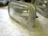
I’ve been working on the headlamps (Vauxhall Viva) , well actually finishing off something I started about 18 months ago. Backing plate is 3mm aluminium with riv-nuts to take M5 studs for the adjusters. The plate is bonded to the fibre-glass using Tiger-seal
I’m using 5¾” spot lamps in the lower cut-outs, so I fabricated some M5 mounting studs that have been bonded in again using Tiger-seal
Headlamp closure panels have been made using a simple mould using some scrap ABS sheet and a small food container. After coating with a release agent a simple fibre-glass panel was moulded and fettled. I was originally planning to buy these from Sourthern GT, but they didn't have them in stock when I ordered a few other bits, so in the end they only took a couple of hours to make, which was more satifying than handing over cash!
The cable ties bases I’ve used for the side indicator wires, are the ones with the self adhesives pads fitted and IVA inspectors are know to fail these, as they eventually come off. To get around this I’ve stripped of the self adhesive pad and bonded to the fibreglass using tiger-seal again - these are never going to come off now!
Regards
Andy
Attachments
-
 Light 5.JPG147 KB · Views: 575
 -
 Light 4.JPG127.6 KB · Views: 595
 -
 Light 2.JPG138.5 KB · Views: 593
 -
 Light 1.JPG164.6 KB · Views: 595
 -
 Light 3.JPG155.7 KB · Views: 582
 -
 Light 6.JPG165.3 KB · Views: 575
 -
 Light 7.JPG173.3 KB · Views: 571
 -
 Light 8.JPG139.4 KB · Views: 628
 -
 Light 9.JPG131.8 KB · Views: 636
Last edited:
Very close Keith - Suitable for microwave use!!
As you say not expensive to buy, but more money to spend on other goodies!
Regards
Andy
As you say not expensive to buy, but more money to spend on other goodies!
Regards
Andy
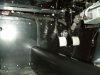
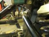
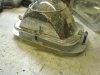
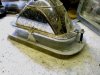
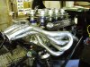
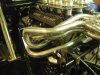
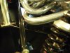
The exhaust is now fitted for first time post ceramic coating. All the header bolts have been drilled to allow them to be lock-wired, once the gaskets have settled after first engine start
To prove I’m as a useless as the next man, check out my lack of clearance between the freshly coated header pipe and the suspension trailing arm!
I’m sure I trial-fitted the arm during fabrication and there’s plenty of clearance on the other side. I think I was trying to get the maximum length in the pipe to equalise the runner lengths. Fortunately it looks like at nominal ride height there’s minimal clearance, but I think post-IVA, it’s going to have to come off and be re-done which will be a real ball ache!
Regards
Andy
Attachments
A small mistake Andy , easily rectified... Looks Very nice.
I did not use any exhaust gaskets, apparently not many people do they use heat resistant silicon, it actually does make it easier.
Silicon may also not be as thick as the gasket so may increase the gap ?
When setting up the suspension for IVA you may need to adjust that arm anyway... as long as it's away from the exhaust that's ok.
As regards drilling bolts, I was informed that the engine mount bolts often work loose too, so I'll be keeping an eye on that
Hi Keith,
As you say, it’s not a big job to rectify, it’s more of a pain that I didn’t check more thoroughly when I was making it. I think I was more concerned about getting the runner lengths to match that why it’s pushed out so far.
Thanks for the head-up on the engine mount bolts. On mine, the mount to chassis bolt used a nyloc nut, but I will take out the the engine to mount bolts & threadlock them all.
Regards,
Andy
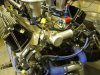
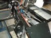
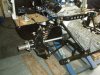
I’ve now made up the front & rear clip harnesses and they connect to the main harness using waterproof connectors.
With the battery connected up for the first time, through a 20A fuse in case anything goes wrong, testing the electrical system only highlighted a few minor issues that needed resolving (not enough feeds to the hazard light switch and the brake fluid warning light that didn’t work). So far there no significant issues and I’m really chuffed as this is a significant step in actually completing the car. Attached are obligatory photos of the headlights working and as the rear clam mounting brackets were off being modified, the rear lights are tested on the floor!
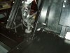
All the gearshift is now in and working. I’ve added the micro adjuster as an after thought as I realised my original design had no adjustment, as all the ends and U-J’s were fitted with roll pins. I’ve still got to make cover up which it will need for the IVA. The micro adjuster will be covered with heat-shrink to further blunt all the edges
Regards
Andy
With the battery connected up for the first time, through a 20A fuse in case anything goes wrong, testing the electrical system only highlighted a few minor issues that needed resolving (not enough feeds to the hazard light switch and the brake fluid warning light that didn’t work). So far there no significant issues and I’m really chuffed as this is a significant step in actually completing the car. Attached are obligatory photos of the headlights working and as the rear clam mounting brackets were off being modified, the rear lights are tested on the floor!
All the gearshift is now in and working. I’ve added the micro adjuster as an after thought as I realised my original design had no adjustment, as all the ends and U-J’s were fitted with roll pins. I’ve still got to make cover up which it will need for the IVA. The micro adjuster will be covered with heat-shrink to further blunt all the edges
Regards
Andy
Attachments
Hi Keith,
read the words, not just look at the picures.... :laugh:
"I’ve still got to make cover up which it will need for the IVA. The micro adjuster will be covered with heat-shrink to further blunt all the edges"
Regards,
Andy
read the words, not just look at the picures.... :laugh:
"I’ve still got to make cover up which it will need for the IVA. The micro adjuster will be covered with heat-shrink to further blunt all the edges"
Regards,
Andy
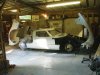
While the weather still reasonably warm, I thought I better have another session on getting the trying to get the body to fit.
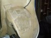
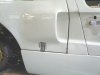
With the spider section bolted in, the fit of doors & the front clam was OK, but the rear clam was no where near. The basic issues were:
The previous owner had basically trimmed the doors wrongly, so the tops of the door edges had to be re-built with chopped-glass filler. These will be finally aligned & filled when the doors seals arrive.
Regards
Andy
With the spider section bolted in, the fit of doors & the front clam was OK, but the rear clam was no where near. The basic issues were:
- On the off/side closure to the sill was too far in-board by 20mm
- On the near/side the clam did not close parallel to the sill, despite other datum’s being correct
The previous owner had basically trimmed the doors wrongly, so the tops of the door edges had to be re-built with chopped-glass filler. These will be finally aligned & filled when the doors seals arrive.
Regards
Andy
Attachments
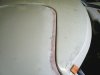
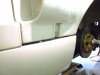
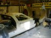
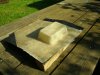
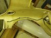
The dash to door fit was very poor, basically the lines don’t flow properly between the two surfaces i.e. there is a taper of 5-20mm down the edge of the door compared to the dash. The dash was originally aligned to be central to the door posts and the steering column centre-line, so I was surprised when the fit is so bad.
This has been corrected by slitting the doors & taking a wedge section out and then re-glassing & filling it on the driver side and adding material to the passenger door – it doesn’t mention anything in the Tornado build manual about this !!! :laugh:
Note this is made a lot easier by heating the surrounding f/glass with a hot air gun to soften the resin
Regards
Andy
Attachments
Who's body is that Andy ?
It sure looks like more work than it should have done on it.
All these years that GT40 replicas have been going and there's still no one that makes a near perfect fit body and I know it is achievable.
I think some of the manufacturers moulds must be pretty over used by now and there's so much cutting and trimming needed to get things looking good.
When you compare an Ultima body that straight from the gel coat it lines up with minimum trimming required.
I honestly believe that you can fit and align an Ultima body and doors in 1 day.
Hi Andy,
Great job so far. I've had a lot of issues with my MDA body. In the end I've gone with Southern GT Sills and doors to help achieve a better fit. These are supplied by Lee Dawson. They fit near perfect to my car and I'm very pleased with them. It's a pain to have these alignment issues though. I don't know what the Tornado body is like but the MDA shell was pretty inconsistent (Thick fibreglas in some areas and too thin in others), although the Spider and Front and rear clips were o.k.
With your eye for detail and precision, I'm sure you will achieve what you want but it does take time if what you have to start with is not great.
Good luck.
Martin
Hi Martin, Keith,
It’s a Tornado body and based how many of these kits have been sold (supposed to be over 800) I was surprised how poor the fibreglass quality is.
Putting aside the poor fit issues; the gel-coat is extremely thin (translucent in places) and panels thick enough only to support the required shape. Compared to the panel thicknesses I’ve seen on GTD’s, RCR’s & Lee Dawson supplied bodies I can only presume I’ve a light weight fibre-glass body, but the invoice I have for the original builder doesn’t state it. It is consistent in thickness though – thin everywhere!
It also doesn’t incorporate any steel reinforcements in the doors that the current website proclaims and there’s a loads of air bubbles in the return edges, I’ve been slowly knocking out and then filling, so generally not impressed
Regards
Andy
If you haven't looked my Ultima Un Build thread in the wings, wheels and keels section have a look at it, that is a Gel coat straight from the mould and I have only sanded of a small area of 75mm " ish " so far to get the gaps as you see them.
It can be done.
If you have air bubbles in the corners that's just poor moulding but fear not as you know it's all do able.
IVA ON MY FORTY THIS THURSDAY.. YIPEE ..
It can be done.
If you have air bubbles in the corners that's just poor moulding but fear not as you know it's all do able.
IVA ON MY FORTY THIS THURSDAY.. YIPEE ..
Similar threads
- Replies
- 4
- Views
- 2K