
You are using an out of date browser. It may not display this or other websites correctly.
You should upgrade or use an alternative browser.
You should upgrade or use an alternative browser.
A Riviera scratchbuilt GT40
- Thread starter REJ01
- Start date
Jac mac, Mic
I clearly understood your warning and I will wait to get oil pressure before any motor spinning! Thank you for the wise advice ...
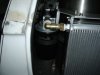
Effectively Mic,I already made the starter electrical test, and I wanted to check the starter pinion engagement on the flywheel ring ; but this is not really a major issue as the pinion/ring gap is adjustable .
Going ahead on the 908 project Mic ?
I clearly understood your warning and I will wait to get oil pressure before any motor spinning! Thank you for the wise advice ...
Effectively Mic,I already made the starter electrical test, and I wanted to check the starter pinion engagement on the flywheel ring ; but this is not really a major issue as the pinion/ring gap is adjustable .
Going ahead on the 908 project Mic ?
Hello
Yes that's a good decision to wait until engine is more fit with accessories !
And yes thanks 908 project is on the bench !!
I just found a very nice rebuilt 3 l RSR engine ( waiting for Calberson delivery next week !)
Finally I decided to go with a 915 gearbox am starting to rebuilt with LSD and brand new gears ( so less work to adapt to the 6 cyl !!)
Waiting too my bodywork and laser cut tubes for chassis end of november
May be I will start somewhere in the froum some built thread ?
what are your others "work in process" actually ?
Nice to see that your very interesting Porsche 908 project is on the right direction ...
As you mention, you obviously need now to open a build thread on the forum and not doubt that the forum administrators will propose a place for that!
To the question of present "Work in process" on mine, I am mainly focused on the electrical installation .
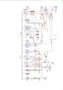
As said on a post ago , here are attached the Excel electrical main schematics ; not very friendly to understand for others ! but may give some ideas or generate some remarks ....
My main objective is to have a flexible, expansible ( No ventilation, nor AC for the time being...) system and avoid to route extra cables all along the chassis .....
As you mention, you obviously need now to open a build thread on the forum and not doubt that the forum administrators will propose a place for that!
To the question of present "Work in process" on mine, I am mainly focused on the electrical installation .
As said on a post ago , here are attached the Excel electrical main schematics ; not very friendly to understand for others ! but may give some ideas or generate some remarks ....
My main objective is to have a flexible, expansible ( No ventilation, nor AC for the time being...) system and avoid to route extra cables all along the chassis .....
Attachments
Your plant seems to be ok ; to disconnect front and rear bonnets you will need to have some plugs what do you plan to source ?
Good stuff on these are advisable because it's to me a point where using cheep solutions is ducting to future issues !!
Don't know if you can source also some good "aeronotics " brand for wires but may be you can find near your place some friend working at Aérospaciale and ask if they have second hand harnesses where to pick out that very nice white wires ( they are light and strong !!!)
Keep on your good work
bon courage
Mic,
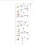
I plan to use "Superseal" connectors , from Radio Spares, Conrad or equivalent; they are (supposed...) to be water proof and I noticed they are installed in engine bay on some large diffusion cars without appearent issues ...( Attached view)
For the electric wires, I went with Auto Electric Supply ( UK) ; interesting "thin wall" wires , accurate delay, fair price ...
A bientôt ...
Attachments
Hi all,
These last weeks, I worked at the same time on several points...Not the best methology, but it can be efficient when something does not go the right way at the first time!
I when ahead on :
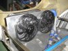
*Exhaust : The global assembly is achieved whith headers welded; I need now to do the final weld on every junction ....
*Radiator : Installed with 12 " fans ; I made a shroud and placed the fans at 50 mm distance of the back of the radiator) ;
*Electrical : I wired the main cables and installed the "Engine electrical box" which is dedicated to the engine links .
*Dry sump : I installed the oil tank ( 12 qtr volume for 10 qtr oil planed ) and the oil cooler with attached filter .
*Engine : I finalised the main belt installation with alternator and idle pulley
The left side of the egine bay is now becoming wery crowded with the oil tank , but I decided to stay on shortest oil lines option between the tank and the oil pump...
René
These last weeks, I worked at the same time on several points...Not the best methology, but it can be efficient when something does not go the right way at the first time!
I when ahead on :
*Exhaust : The global assembly is achieved whith headers welded; I need now to do the final weld on every junction ....
*Radiator : Installed with 12 " fans ; I made a shroud and placed the fans at 50 mm distance of the back of the radiator) ;
*Electrical : I wired the main cables and installed the "Engine electrical box" which is dedicated to the engine links .
*Dry sump : I installed the oil tank ( 12 qtr volume for 10 qtr oil planed ) and the oil cooler with attached filter .
*Engine : I finalised the main belt installation with alternator and idle pulley
The left side of the egine bay is now becoming wery crowded with the oil tank , but I decided to stay on shortest oil lines option between the tank and the oil pump...
René
Attachments
-
 gt40 156 fans.jpg96.8 KB · Views: 1,183
 -
 gt40 157 fans.jpg88 KB · Views: 1,190
 -
 gt40 161 fans .jpg83.3 KB · Views: 1,125
 -
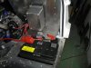 gt40 159 battery.jpg87.2 KB · Views: 1,108
 -
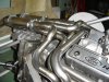 gt40 160 exhaust.jpg94.7 KB · Views: 1,232
 -
 gt40 162.jpg92.8 KB · Views: 1,138
 -
 gt40 163 dry sump tank.jpg82.6 KB · Views: 1,158
 -
 gt40 163 oil filter.jpg79.1 KB · Views: 1,102
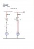
Going ahead on the fuel system, I would be pleased to get advice from the experienced people , on the fuel pump subject :
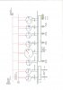
I plan to use a Carter 4601 GP fuel pump ( Rotary vane ) , connected as shown on the attached schematic , with by-pass pressure regulator , return line, and two 3-ways tanks selection valves .
My main question is on the installation height capacity : Carter announces 24 inches possibility above the bottom tank on the installation instructions as shown attached.. In my chassis,this dimension would be approx 14 " ; so should be OK and I have to say that I have no idea to get less!
By the same time most rotary-vane competitors ( Holley, Edelbrock ...) says : never install above the bottom tank, or at least the fuel level !
Are they too much conservative, or Carter is too much optimistic, or have a more performing and reliable rotary vane solution ?
I did not ordered the pump yet , so I can switch to another solution, but still in the 14 " or close, height constraint ....
Attachments
Terry Oxandale
Skinny Man
For many years, I used the Holley design at a point about 2" (measured at the inlet port) above the top/front edge of the fuel tank, which was roughly 14" above the sump built into the bottom/rear of the tank. I could draw fuel even with a fresh hose (empty hose), and through the filter, from the tank to the pump, so priming wasn't necessary for it to draw fuel.

This is a very valuable information for me , thank you Terry ...
I feel now much more confortable to go ahead on a similar disposition ....
I addition, when investigating previously on different forums on the Carter design , I understood ( but not confirmed ...) that the motor is cooled from the fuel , related to this seldom "motor down" design , and some "siphon" effect is to be expected at each priming sequence ( Exept the very first one !) this may be the reason why Carter commits to this important 24 " lift height ...
rené
Terry Oxandale
Skinny Man
You're very thorough from what I've seen here, but I'll note it anyway. Don't run these pumps dry (not even a little bit). What I did, prior to actually using fuel (gasoline) to test the entire fuel system, was use mineral spirits as the "guinea pig" fluid. Then pumped it all out when I was happy that all sensors, tanks, pots, hoses, and fittings were clean, functional, and trash free, and then replaced it with real fuel. Mineral Spirits also has a great "wetting" action that will seep through even the smallest of leaks.
I don't believe the holley design is fuel cooled (unless it is solely by conductance of heat through the motor shaft/vanes). The reason I say this is that when I had the pump mounted lower and in front of the tank, the exhaust pipe heat was evidentally causing an over-temp cut-off switch to operate in the pump. The pump would turn completely off in stop and go traffic, or heavy idling (but the fuel was still cool). Once I moved it up and out of the heated environment, it never quit on me.
I don't believe the holley design is fuel cooled (unless it is solely by conductance of heat through the motor shaft/vanes). The reason I say this is that when I had the pump mounted lower and in front of the tank, the exhaust pipe heat was evidentally causing an over-temp cut-off switch to operate in the pump. The pump would turn completely off in stop and go traffic, or heavy idling (but the fuel was still cool). Once I moved it up and out of the heated environment, it never quit on me.
Last edited:
I closely keep in mind your preparation and test procedure Terry , and I will apply when needed....
All these fuel related things seem so sensible for me, that every experience feed-back is an asset to get it working ...
René
All these fuel related things seem so sensible for me, that every experience feed-back is an asset to get it working ...
René
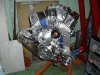
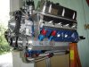
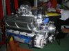
I finally came to the step to have the engine assembled and almost ready for the final installation in the chassis ...
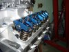
Most of my working time ( Only a few hours per weeks....) was focused on the valve train installation, as it was a total new area for me ( My experience is more on 2 strokes go-kart engines !).
The cylinder heads are Edelbrock RPM Performer ( 2.02-1.9 valves ) with 1.6 ratio rockers arms ; the camshaft is the Edelbrock SADI associated part , not very aggressive .
The lifters are hydraulic rollers.
With the flat top Mahle pistons, I expect to get approx 10/1 compression ratio.
I have recently installed the fuel pumping system with 1 pump ( Carter ) only and two 3 ways valves ; I installed a fuel regulator , with return lines .
The external dry sump oil pump ( NRC) is in place and I confirm that the SS braided hoses ( AN 12) installation is real nightmare !
For oil priming operations, I plan to drive the pump with the same belt and an electric drill ...
Next step is to finalise the ignition system and install the engine in the chassis; and then I will have to thinck at the start up procedure ....
Attachments
-
 gt40 165 engine.jpg75.2 KB · Views: 924
 -
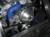
 gt40 166 Engine.jpg112.7 KB · Views: 874
 -
 gt40 167engine.jpg135.9 KB · Views: 874
 -
 gt40 168 Engine.jpg113.3 KB · Views: 827
 -
 gt40 170 Rocker arms.jpg98.1 KB · Views: 876
 -
 gt40 174 Fuel pump.jpg94.1 KB · Views: 1,076
 -
 gt40 176 Engine bay.jpg84.8 KB · Views: 965
 -
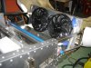
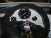 gt40 177 Instruments.jpg75.9 KB · Views: 936
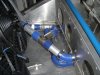
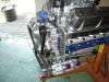
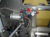
Very nice Rene... I don't know how you plan on connecting drill motor to that drysump pump, but they take a LOT of torque to turn over under pressure. You may want to just run it off the belt and remove the spark plugs so you can use the starter motor for periods of 30 seconds with a 2 min cool down for the starter.. This also will get you full distribution through your valve train.
Good point Randy , I don't effectively know how much power/torque will need a fair oil pressure set up ...
From theory , Power = delta pressure x flow , and with 65 psi pressure at 40 GPM , calculated power is approx 330 Watts .
With a conservative 2/1 efficiency ratio this gives 660 Watts which is in the range of a medium power electric drill .
But this is only estimation , and any effective experience on this subject would be of very high interest !
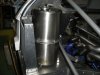
If applicable , I plan to hold the drill on the chassis , from inside cockpit ( see picture - pump not yet in place - driver side ) with a specific (removable!) braket.
Any way, I keep in mind your suggestion to spin the engine with the starter , and thus get oil flowed trought the complete valvetrain ...
From theory , Power = delta pressure x flow , and with 65 psi pressure at 40 GPM , calculated power is approx 330 Watts .
With a conservative 2/1 efficiency ratio this gives 660 Watts which is in the range of a medium power electric drill .
But this is only estimation , and any effective experience on this subject would be of very high interest !
If applicable , I plan to hold the drill on the chassis , from inside cockpit ( see picture - pump not yet in place - driver side ) with a specific (removable!) braket.
Any way, I keep in mind your suggestion to spin the engine with the starter , and thus get oil flowed trought the complete valvetrain ...
Attachments

I primed my engine (wet sump) yesterday. Standard procedure with a dizzy replacement shaft and a manual electric drill. even i have only a standard sbf oil pump ( no one realy needs one of this high volume pumps if everything is set up correctly on the engine) my 650 Watt drill needed a brake after 2- 3 Minutes. Rene somehow the viscosity of the oil has to come into your equation. I use Valvoline 20 W 50 VR 1 mineralic racing oil, which is quite viscous when cold. So it would defenitely help if you warm up your oil to around 50°C or more ( just don´t burn yourself). Would make it much easier for your drill. Also it is not about the pressure in preoiling. So use a low gear on your drill . THere is no need for a permanent rotation to get the valvetrain lubed. just have some one turn the engine in 90° steps every 10 secs or so then after around 3 minutes you should see oil coming out at the rockers ( at least it is the case with my flat tappet engine).
One thing. Check the forum, but i seem to remember that we had some discussion on those blue ( or red) scorpíon rockers. Don´t remember what the content has been , but there was something
TOM
One thing. Check the forum, but i seem to remember that we had some discussion on those blue ( or red) scorpíon rockers. Don´t remember what the content has been , but there was something
TOM
flatchat(Chris)
Supporter
Have you done the flywheel yet --looking at the end of the crank flywheel flange going clockwise is 60° - 60° - 60° - 60° - 56° - 64° 7/16" UNF on 3" PCD ( ie 11.1dia mm on 76.2mm PCD)
Unless you have a 302W I don't know about ?
Great build BTW
Unless you have a 302W I don't know about ?
Great build BTW
I fully appreciate your experimented procedure TOM, thank you ;I will stick to it and I may have the possibity to directly heat up the oil in the oil can , with plunger electric resistor ...
I plan to use 15W/40 mineral oil with ZDDP additive for the break-in , despite I have roller lifters ...
About the Scorpion rockers, in fact, I made a large survey on several Cobra, Mustang and others websites , before purchase; the result was fairly positive ...
I have to say that I focused a lot of attention on the valve train geometry , and I selected the push rods lenght from tests with an ajustable pushrod ( Comp Cam )
Yes FLATCHAT , I already have the flywheel , home made, and I am very proud to say that the flange has been machined exactly as you detail it !
Thank you anyway for your expert advice ..
As visible on the schematic,(Forgot to take pictures..) it is aluminum alloy made, with a steel Fidanza insert; no balance weight as the crank is internaly balanced; Porsche 965 clutch and G50.00 box; I made a serious flywheel+clutch balance but I am already a little bit anxious for the first start up!
René
Attachments
Similar threads
- Replies
- 7
- Views
- 758