
You are using an out of date browser. It may not display this or other websites correctly.
You should upgrade or use an alternative browser.
You should upgrade or use an alternative browser.
A Riviera scratchbuilt GT40
- Thread starter REJ01
- Start date
Terry Oxandale
Skinny Man
Thanks for the comments Terry,
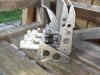
The hubs /bearing donors are AUDI A6 or A4 , European models:
*Rear is a 82 mm OD bearing - Hub as shown on the picture , with a 38 splines drive, in order to match with VAG Transporter half-shafts I plan to install .
Bearing holders are still to be machined from 7075 ally....
*Front are 75 mm OD bearings , smaller hub , and similar bearing holders than rear
All this stuff may be a little bit heavy , but it should do the job ....
René
Awesome work! You've got me looking into a similar fabrication with a different hub assembly. Just curious, will you have a crush-tube, or some means of preventing the drawing together of the two lower stubs of your upright when you tighten the lower spindle nuts (attaching the lower rose joints to the upright)?
Terry
Thanck you Steve26, Terry for your encouragements; it is allways nice to get approvments from people who knows...!
Terry, your question is a good one! ; I plan to install 25 mm OD/16 mm ID 2017 ally crush-tubes, but I did not machined them yet ....
In fact ,after the main machining work, I am starting the process to come back on every assembly on the suspensions and the chassis, and check for every needed, crush-tubes, adequate washers, holes for future locking wire etc ....
To complete the engine/box views, I attach the flywheel drawing which I used for machining; the 1045 steel insert is a Fidanza 229 501 ( 240 mm) I got from Summit.
Attachments
Thanck you Wynand;
I sent you a mail this day; the miscellaneous Soliworks files are available ....; only needed : a "heavy files" transfert solution ...
I sent you a mail this day; the miscellaneous Soliworks files are available ....; only needed : a "heavy files" transfert solution ...
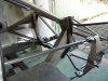
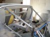
By the same time, I went ahead on the engine-box assembly, I continued working on the chassis , panelling and sub-structures installation.
At the present time, I consider that the metal work on the chassis is finished (Exepted the wheel bearings) , and I am now coming to all the remaining "details" which will probably cost more time than the main construction itself...
I started "machining the metal" 3 years ago , and I expect at least 2 years more to get the car on the road , but not finished ...
Attachments
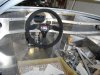
You are wellcome Randy ; I had the opportunity to check this last weeck-end if the job made on the "visible" things was also applicable on some mecchanical parts I made ...
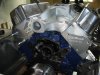
I installed the custom releasefork I made for the G 50 gear box ( Lateral lever) in order to clear the main bottom rail of the engine bay ...
The lever is actuated from a BMW E 36 slave cylinder and the master is a .625 " Wilwood installed in the pedal box I made at the very begining of the build ...
The clutch is a 240 mm Porsche 965 turbo bolted on the aluminum flywheel
I used the Tom's EGLITOM chart on this subject ( Thanck you Tom ..)as a reference , and the results are really close to the chart data :
Approx 20 kg on the pedal for 120 mm travel at the clutch release...
My main concern was about the fork axis behaviour under effort; not no problems during the static tests I made...
Attachments
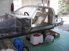
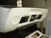
After some time "off" on the forum it is now time for me to wake up and give some update ...!
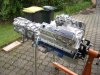
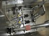
I focused mainly on the engine and exhaust ;
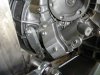
The engine is now almost dressed up, but still without cam and ignition .
I installed the drive train in the engine bay with quite firm 90 shore polyurethane bushes ; with similar design for engine and box.
The cranck axis level is finally 160 mm from bottom floor and the drivetrain height position is given in fact by the G50 box diameter .
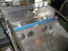
I finalized the dry-sump sump wich is made from a very standard steel wet sump device , with a specific welded bottom face ; 3 x12 AN scavenge fittings are welded on the left side ( Pump will be left side).
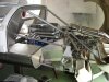
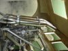
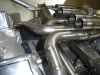
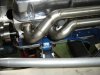
My main present focus is on the exhaust side ;
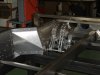
It is a "full Stainless Steel" design and I am working with 42.4 mm OD SS 304 L pipe ; headers flange are 8 mm thick in order to have acceptable rigidity.
I made my own 4/1 merge collectors ( mix TIG and brazing...) but I have to say that I am glad to have them completed !
I am presently building the "bundle of snake" ( spot weld only at this step) and I plan to achieve with circular welding on each junction .
Each muffler line is supported via 3 25 x 10 mm rubber bushings is order to accept some drivetrain movements on its own bushings.
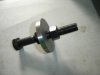
By the same time , I started to make some specific tooling for the engine build up and future maintenance ; ie , damper installer and puller ; tested and seems OK.
I focused mainly on the engine and exhaust ;
The engine is now almost dressed up, but still without cam and ignition .
I installed the drive train in the engine bay with quite firm 90 shore polyurethane bushes ; with similar design for engine and box.
The cranck axis level is finally 160 mm from bottom floor and the drivetrain height position is given in fact by the G50 box diameter .
I finalized the dry-sump sump wich is made from a very standard steel wet sump device , with a specific welded bottom face ; 3 x12 AN scavenge fittings are welded on the left side ( Pump will be left side).
My main present focus is on the exhaust side ;
It is a "full Stainless Steel" design and I am working with 42.4 mm OD SS 304 L pipe ; headers flange are 8 mm thick in order to have acceptable rigidity.
I made my own 4/1 merge collectors ( mix TIG and brazing...) but I have to say that I am glad to have them completed !
I am presently building the "bundle of snake" ( spot weld only at this step) and I plan to achieve with circular welding on each junction .
Each muffler line is supported via 3 25 x 10 mm rubber bushings is order to accept some drivetrain movements on its own bushings.
By the same time , I started to make some specific tooling for the engine build up and future maintenance ; ie , damper installer and puller ; tested and seems OK.
Attachments
-
 gt40 144 rear.jpg96.2 KB · Views: 2,369
 -
 gt40 138 Engine.JPG316.9 KB · Views: 3,595
 -
 gt40 146 engine from cockpit.jpg83.7 KB · Views: 1,352
 -
 gt40 149 exhaust.jpg82.6 KB · Views: 2,811
 -
 gt40 150 exhaust.jpg72 KB · Views: 1,221
 -
 gt40 merge muffler 145.jpg86.7 KB · Views: 1,809
 -
 gt40 153 bundle of snake.jpg100.4 KB · Views: 1,484
 -
 gt40 154 headers.jpg95.1 KB · Views: 1,329
 -
 gt40 151 pedal box.jpg99.1 KB · Views: 1,612
 -
 gt40 152 damper install tool.jpg93.7 KB · Views: 1,208
Thank you Randy , GTRene fort your comments;
The routing of the headers is a quite long process, but not so difficult, and my engine bay is reasonnably wide; this gives some flexibility for the optimum route to choose....
I tried to stick on the cross-flow and swirl effect dispositions , but I have to say that I finally decided to switch pipes from cylinders 6 and 7 , going to right merge , for easier installation !
A question I have : What may be the impact of any gaz leaks on the pipes links ( mainly at merges and mufflers level) when engine is running : Noise, carburation problems, heat, others...?
At those points, the insertion lenght between exterior and inside pipe is approx 40 mm long and diameter gap is approx 0.1 to 0.3 mm
Rene:
Beautiful job on everything, I love attention to details.
It looks like you are using a slip-fit on the collectors for the individual tubes. This works quite well especially with the tight tolerance you have, you will get a few small leaks that you may not even hear, and after a while the fit will carbon up a bit and be fine. I have seen headers that leak a bit on startup but quiet down real fast as the temps rise....I think you will be OK on your setup.
Great build...keep posting
Cheers
Phil
Ian Anderson
Lifetime Supporter
Rene
Use greas on the headers etc where they fit inside your merge collectors.
With the heat the greas will seal any leaks
And when you need to take them apart again the grease should help
Exhause sealer will seal any leaks but when you come to take it apart will stick like glue!
Ian
Use greas on the headers etc where they fit inside your merge collectors.
With the heat the greas will seal any leaks
And when you need to take them apart again the grease should help
Exhause sealer will seal any leaks but when you come to take it apart will stick like glue!
Ian
Two different things you can use that will tolerate the heat.
1) Antiseize Compound
2) Red or Copper high temp RTV from Permatex (I also use this instead of header gaskets and it works very well)
Both will allow you to disassemble later, but the RTV is a little bit tighter bond..
1) Antiseize Compound
2) Red or Copper high temp RTV from Permatex (I also use this instead of header gaskets and it works very well)
Both will allow you to disassemble later, but the RTV is a little bit tighter bond..
Prompt and precise feed back to my question ! Thanck you all.
I will use first the "grease" solution and investigate the Permatex suggestion ..
I will use first the "grease" solution and investigate the Permatex suggestion ..
Hello
Congrats for your built , very neat and skilled construction !!
May I give you some confirnation for your exhaust tubes ;
Remember that this exhaust will get some good temp when running and that stainless will go on bigger dimension on the outside tube diameter quicker on those directly connected to the engine than the four in one so your clearance will be quite close to zero and no leak or very very fiew !!
Hope you plan to weld on top to each upper tubes and four in one sleeves some small brackets in order to join both part and have them close together once gaz pressure tends to push muffler to the rear ??
Keep on your very nice work
Hello Mic,
Welcome to this forum and thank you for the jugment on my work and your skilled advices ....
Sorry for the time to answer ; I was more in the garage on WE than on the forum ...
I had in mind to install some links between the header side pipes and the 4/1 merges ( As seen on numeros engines pictures), but I had no very effective reason to do it ...Now, I have !
I will install those brakets after all tubes routing, and final welding
rené
By the same time I am completing the exhaust lines, I started the electrical installation , with the idea to have the engine cranked up in some future ...
I went for a "flexible" electrical design, with 3 junction boxes ( engine, dash, front) in order to have some modification capability if needed ....
I also included some safety capabilities as : Ignition shut off under 7 psi oil pressure ( But can be desabled ...), Fans overide ....
(I will post in a few days the Excel file showing the main features of the design)
Presently, I can activate the electrical starter and this leads to a question for the "engine guys" ....:
Despite the oil dry sump pump, nor the valve train and ignition are not installed ( Chrismas gifts, to come...) , is it reasonable to test the engine rotation with the starter in order to have a first level check ?
I had in mind to fill the dry sump pan with 3 ou 4 quarters of oil, in order to have the cranck "sloshing" in oil and cylinders "oiled" by the same time ; but this may not be the best way to operate !
Thanks for advices or experience feed back....
René
Hello René good to read you again !!
Concerning your test one advise can be to undo all sparkplugs in order not to have compression torque in your engine , this test can be done for only very few seconds only making sure you have enought oil in because normaly as soon as you rotate engine ( even in low revs ) your oil pump will work and start to lubricate all circuit specially if the relief valve pressure is set to working pressure
Normally this process is used on new engine set up to start pressurising oil so a good advise will be to have oil level done !!
But if you do not have valves in there will be probably lot of oil leaking every where in the engine ?? or am missing something in your question ?
Why do you want to proceed to such a test ?
amitiées
Similar threads
- Replies
- 7
- Views
- 969