Mark's GT-R Build

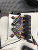
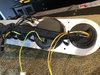
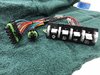
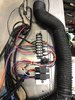
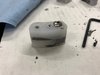
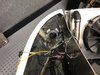
The wiring is almost complete. This one relay board is just used to control the running lights, turn signals and four way flashers, so that the running lights will shut off it either that side turn signal is used or of the four way flasher is used.

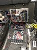
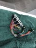
This look a little messy now, but it will be organized and neat when I am done.
 

Attachments

  • IMG_6266.jpg
    IMG_6266.jpg
    56.5 KB · Views: 673
  • IMG_6267.jpg
    IMG_6267.jpg
    80.2 KB · Views: 701
This is the dash gauge set final wired and organized. I want the final install of every component to be as easy and least likely to get scratched as possible, so these wires needed to be wrapped.
 

Attachments

  • IMG_6268.jpg
    IMG_6268.jpg
    79.3 KB · Views: 704
  • IMG_6270.jpg
    IMG_6270.jpg
    80.5 KB · Views: 641
  • IMG_6271.jpg
    IMG_6271.jpg
    77.1 KB · Views: 626
The members of this forum have helped me again. Luke S suggested I consider adding billet louvers to the rear clam to add to the look already started with the carbon fiber intake and valve covers. I never really considered it until he mentioned it. He was absolutely right. They look great. H used them so I should have been more alert to see then in his build. Thanks Luke for following the build and making the suggestion. At the beginning of my build, Ken suggested a change in the air cleaners and the diameter of the intake tubing leading the throttle bodies. He was also absolutely right. Wait until you see what that that looks like when I have that finished!
 

Attachments

  • IMG_6293.jpg
    IMG_6293.jpg
    36.8 KB · Views: 673
  • IMG_6294.jpg
    IMG_6294.jpg
    47 KB · Views: 583
  • IMG_6295.jpg
    IMG_6295.jpg
    39 KB · Views: 668
Still working on the wiring, getting closer to having it finished. This is the switch panel I will be using in the overhead console. Watson Streetworks made the switches. Really nice stuff. Ignition On, Headlights/Running Lights, Fog Lights and Interior Light, all with indicator lamps. I will make a backing plate to the exact shape of the overhead panel indentation out of stainless, then clearcoat red over that stainless panel to match the other red accents. The stainless will only add about a half inch border to the top and bottom, and about 3/4 inch to each end, but it should make the look more precise, given that I could not get and exact fit from Watson's available sizes.
 

Attachments

  • IMG_6296.jpg
    IMG_6296.jpg
    86.8 KB · Views: 690
  • IMG_6297.jpg
    IMG_6297.jpg
    85 KB · Views: 641
I am doing the final steps in wiring and will be testing all of the circuits next week. I also had to work on the clutch master cylinder. The size of the master cylinders that came with the kit included two smaller sizes for the front brakes and the clutch, and a larger one for the rear brakes. In using one of the smaller sizes for the clutch, I found that the volume of fluid movement was not adequate to disengage the Graziano clutch. I ordered a larger master cylinder and got that installed today. Now I have good clutch disengagement with a good pedal pressure.
 
I just received the rear clam hinges I asked H to make for me. Again, the master delivered. The cross brace for re-enforcing the clam is curved to fit the inside of the rear clam perfectly and I know the hinges will work. Thanks H.
 

Attachments

  • IMG_6301.jpg
    IMG_6301.jpg
    68.1 KB · Views: 520
  • IMG_6302.jpg
    IMG_6302.jpg
    79.1 KB · Views: 609
The relays and circuit breaker here may look familiar to most of you. This is my circuit board for the Vintage Air System. After looking at some YouTube videos on installing this system and hearing the pros and cons of reducing the wiring that was provided by Vintage Air, I decided that the people at Vintage Air must know the reasons to install the system as they designed it, so that is what I have done. I just need to add the trinary switch wiring and that system is installed.
 

Attachments

  • IMG_6303.jpg
    IMG_6303.jpg
    73.6 KB · Views: 653
Mark great to see you grab a rear clam shell kit I am doing the same but I assume you will install before me so keep us posted on the installation
 
I have the wiring almost complete, and went through testing each circuit. Most of them tested great, until I got to the circuit involving the Summit Raptor Pro. As soon as I put power to that system, the right turn signal started blinking not having tough any buttons. Pushing the right turn signal button would not turn it off. The only way to turn it off was to push the 4 way flashers. The right turn signal would then only turn on occasionally after repeated pressing the button. I got in contact with Summit Technology, but they said they could not help me, that I had to go through the retainer I purchased if from. So far no response from my contacting the retailer. More to come, I hope. Dead in the water on the electrical until this get fixed.
 

Attachments

  • IMG_6311.jpg
    IMG_6311.jpg
    70.6 KB · Views: 609
The body is the next step. Headlight frames need some fitting.
 

Attachments

  • IMG_6313.jpg
    IMG_6313.jpg
    43.4 KB · Views: 539
  • IMG_6314.jpg
    IMG_6314.jpg
    43.8 KB · Views: 556
  • IMG_6320.jpg
    IMG_6320.jpg
    45.7 KB · Views: 514
Used some plaster to make the mold to extend a few areas. After roughing up the areas needing additional material, I added the fiberglass. Selective spot trimming and finally got a reasonably fit. This is the before.
 

Attachments

  • IMG_6324.jpg
    IMG_6324.jpg
    99.9 KB · Views: 568
  • IMG_6327.jpg
    IMG_6327.jpg
    96.1 KB · Views: 550
  • IMG_6317.jpg
    IMG_6317.jpg
    51.7 KB · Views: 551
  • IMG_6326.jpg
    IMG_6326.jpg
    47.7 KB · Views: 541
I will be painting the inside of the headlight buckets silver, matching the strips color. The headlight are in position, but still need spacers to get their depth correct.
 

Attachments

  • IMG_6362.jpg
    IMG_6362.jpg
    37.6 KB · Views: 585
  • IMG_6349.jpg
    IMG_6349.jpg
    53.9 KB · Views: 594
  • IMG_6361.jpg
    IMG_6361.jpg
    37.8 KB · Views: 501
  • IMG_6328.jpg
    IMG_6328.jpg
    74.8 KB · Views: 508
  • IMG_6329.jpg
    IMG_6329.jpg
    59.5 KB · Views: 515
  • IMG_6347.jpg
    IMG_6347.jpg
    68.3 KB · Views: 546
  • IMG_6348.jpg
    IMG_6348.jpg
    50 KB · Views: 538
Mounting the Fog Lights is a little more complicated than the head lights. The head lights have a trim piece to cover the mounting screws. The Fog Light buckets have no trim cover. I did not want the screws to show, so I used some plastic boards. The Fog Lights needed to be set back an inch from the bucket surface, so I used half inch plastic, shaped it to follow the curve of the light mounting, but made the four mounting spacers allowing space for the light to move within the frame to adjust the focus on the road. I drilled matching sets, but inserted a nut between the two half inch plastic sheet, then screwed the two half in together to make a one in spacer. Contact cement was used tp attach the plastic the back of the bucket.
 

Attachments

  • IMG_5688.jpg
    IMG_5688.jpg
    59.4 KB · Views: 624
  • IMG_6338.jpg
    IMG_6338.jpg
    91.4 KB · Views: 610
  • IMG_6339.jpg
    IMG_6339.jpg
    92.1 KB · Views: 576
  • IMG_6343.jpg
    IMG_6343.jpg
    55.6 KB · Views: 514
  • IMG_6353.jpg
    IMG_6353.jpg
    109.3 KB · Views: 592
  • IMG_6351.jpg
    IMG_6351.jpg
    77.5 KB · Views: 620
  • IMG_6352.jpg
    IMG_6352.jpg
    97.1 KB · Views: 635
  • IMG_6356 (1).jpg
    IMG_6356 (1).jpg
    140.1 KB · Views: 697
Mark two questions where did you get the louvers for the rear tail and how large are those switches if you hold them up to the dash like the original location was back in 2006. I assume you should be close to firing up soon.
 
It is with deepest regret that I inform you all of Mark's passing.
He had been hospitalized over the Christmas period. He had fought hard to regain his health and get back to working on his beloved GT-R but unfortunately I was informed of his passing over the weekend.
RIP Mark Setter
 
Back
Top