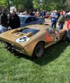
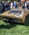
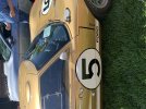
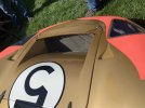
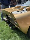
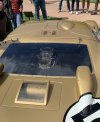
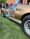
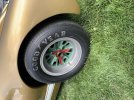
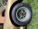
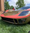
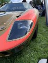
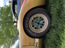
Just happened to be in McPherson KS last weekend at the McPherson College annual car show and got the awesome opportunity to see P1016 in person! What a treat to see it in the wild and on the grounds of one of the unique auto restoration degree programs in the US.
Let me know if anyone wants other close up pics as I took about a dozen for reference to aid in my personal “graduate research project”.
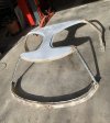
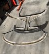
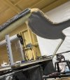
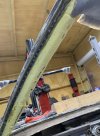
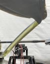
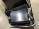
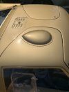
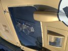
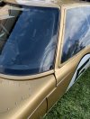
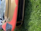
Also got back to some progress on the ‘40’. After completing about 95% of the perfecting of the windshield mount, I decided to work on slicing/splicing and modifying the upper door skins to properly fit them to the rest of the contours of the spider & roof/A-pillar. The driver side was the worst (pics) as it required both the door top and skin in front of the side window to be cut and re-epoxy/fiberglassed.
Due to my slightly larger wheelbase (2”) or the variety of my body panel sources, I am discovering that some of my height dimensions are off by about 3/8-1/2” and will have to split my doors horizontally to make up this difference in the front part of the door. More future pics will make sense once I post them.
View attachment 138947View attachment 138948View attachment 138949View attachment 138950