More scratch building progress and lessons learned.
The main lesson learned was...you don’t know what you don’t know!
Again in an ideal world, you have all the parts ready and waiting so you can measure and make room for it all to work together but that isn’t realistic in any custom car building scenario. First off, I ordered the Wilwood 3 pedal assembly hoping I could make room around my steering shaft & rack but mainly selected it for the fact that it has an integrated throttle pedal and homogenous & high performance look. After initial mock up and measuring the assembly as well as the master cylinders, I realized that the steering rack needed to be raised all the way to the top of the pocket and suspended from the top versus the vertical face of the firewall. Once relocated, I realized that I needed to separate the clutch pedal from the rest of the assembly to gain space from the steering shaft & clearance from the rack gearing and masters on the front side of the firewall.
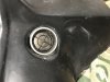
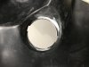
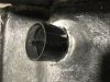
On another note, my new hydraulic hole punch paid off in saving so much work and made nice professional looking holes for the master cylinders. I did pretty much max out the capability of this model and had to take 3 bites/slices at each hole since it was working through 2.6mm/12 gauge mild steel. But I can see using it more in the future and may experiment with using it for dimpling as well.
Also spent time reworking the drivers seat now that I have a “wet cement” location on the steering, dash, and pedals. What I found out was my plan to use a 7/8” thick seat slider was too high for my 34” inseam and knees were hitting the dash bottom. After some careful measuring and sweating in the Texas heat, I was able to make an offset bracket for installing the seat sliders on the sides of the seat! The AP chassis design has 20” wide floors between the tanks and center backbone...I used up 19.5” with this configuration, leaving plenty of room for paneling and installation. This bracket not only lowered the rear of the seat nearly an inch (now just fractions of an inch above the floor) but also added more seat back recline and boosted the thigh support! Works so much better now, is more comfortable, more leg room, headroom, and is adjustable for any shorter drivers (I’m 6’1”). It worked so well that I may even need to bring the seat forward a notch or two to reach the pedals comfortably! I will remind all those that haven’t been following from the start that I did plan and built my GT40 with a 2” stretch in the wheelbase of which I’m using about an inch in the cockpit and 1” in the engine compartment (hopefully making for a smooth rear firewall and not having to notch the cross support for the distributor).
Couple of side notes. 1) the lower control arm “floor humps” DO NOT need to be as large as the plans called for. They WILL require some cutting and re-Engineering to allow my size 12s to use the clutch without obstruction and better comfort. 2) my stock Boxster shifter assembly will fit nicely and will require the center console to be 5” wide. This was planned for and will intrude into the passenger seating area but I will keep the under seat mounted adjustable slider and incorporate a front riser to aid in headroom and seat back recline...why a passenger adjustment? I am thinking rather than removing the seats for rear bulkhead removal and access, I can just slide the seats forward approx 7” and have access the the panel an front of the engine. 3) I will have to widen the drivers seat actuator and possibly shorten its length as well to finish it all up.
View attachment 131565View attachment 131566View attachment 131567View attachment 131568View attachment 131569

") . Maybe next time?!? LOL. I do think there would be room in the Active Power platform and especially making it from scratch.
. Maybe next time?!? LOL. I do think there would be room in the Active Power platform and especially making it from scratch.