A Riviera scratchbuilt GT40

Related to Eddie's question about the adjustments I made to fit the GTSTUNING MKI body, you will find attached a pdf file as summary of the 3 main dimensions I finalized after the body delivery .

Of course, all the "secondary level" dimensions are to be accordingly adjusted...
For me, I made the adjustments "on the field" , without specific new drawings ...

Anyway, from my recent experience, I would say that the sooner you get the body , the better it is...

In the future, if others scratchbuilders get experience with another body type, and a similar or close chassis, it would be interesting to get their revised dimensions.

To be discussed in the right section , of course ....

René
 

Attachments

  • Chassis drawing revised May 2011 body.pdf
    793 KB · Views: 1,945
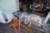
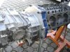
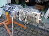
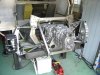
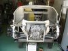
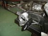
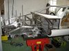
Since my previous posts, I focused mainly on the drivetrain installation :

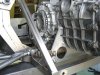
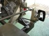
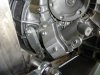
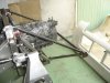
*Porsche G50 box install on the chassis , via 2 polyurethane bushings I made from Shore A 90 PU.

I understood that some ( Experimented...) builders use to bolt directly the engine and box on the chassis; for me, I was a little bit anxious of the :torsion, vibrations and similar, issues , and that is the reason why I used these reasonnably stiff bushings .
I plan to use the same stuff for the engine .
The final input shaft/cranck height is 160 mm from chassis bottom

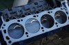
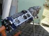
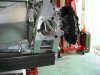
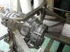
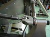
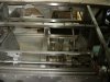
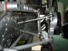
*Lateral fork clutch drive via a specific shaft, similar ( I think..) to the older 930 box ; the hydraulic receiver is from BMW 3 series.
From the first manual tests I made , the clutch bearing is moving ....and the torque to be applied on the shaft is :8 kgm which should lead to approx 25 kg at the pedal.
I received this day all the plumbing/fittings from RallyDesign, and I plan to install soon the hydraulic line .

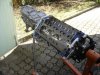
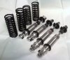
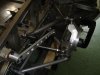
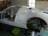
*Rear suspension , almost complete , excepted the shock absorbers.
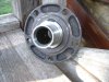
But I still have to work on the uprights, for the bearings and hubs installation.

Can somebody give some advices on the suspension course : I planned on : + 3 inches compressed, and -1.5 inches extended; but it may have to be symetrical? Or other criteria ...Thanks for any inputs on the subject.

René
 

Attachments

  • gt40 095 drivetrain.jpg
    gt40 095 drivetrain.jpg
    72.1 KB · Views: 2,448
  • gt40 096 rear suspension.jpg
    gt40 096 rear suspension.jpg
    65.4 KB · Views: 1,814
  • gt40 097 box fix.jpg
    gt40 097 box fix.jpg
    74 KB · Views: 1,577
  • gt40 098 rear suspension.jpg
    gt40 098 rear suspension.jpg
    73.5 KB · Views: 2,581
  • gt40 099 box.jpg
    gt40 099 box.jpg
    70.9 KB · Views: 1,733
  • gt40 100 rear suspension.jpg
    gt40 100 rear suspension.jpg
    77.6 KB · Views: 1,847
  • gt40 101 clutch actuator.jpg
    gt40 101 clutch actuator.jpg
    60.5 KB · Views: 1,555
  • gt40 102 clevis.jpg
    gt40 102 clevis.jpg
    68.8 KB · Views: 1,813
Hi Rene,

If you can tell me the overall length of your shock absorbers, at full droop and at ride height and if possible at full bump (where floor would hit the ground) i can help you specifiy them.

I'm just CAD modelling my shock kit at the moment i can send that over if it helps.

D.
 
I appreciate your support proposition D.
Here are the main sizings I measured yesterday on the chassis for the forecasted shocks lenght:

*REAR : - Full bump : 320 mm
- Ride height : 400 mm
- Full droop : 420 mm - Limited by a chassis rail ; can be extended to 435 mm

*FRONT : -Full bump : 250 mm
-Ride height: 320 mm
-Full droop : 360 mm

The upper fixing of each shock is adjustable ( Remote braket) within +/- 20 mm approx
The full extension of the FRONT suspension is only limited by the shock itself; is it acceptable ?

René
 
Hi Rene,

Pic is of the shock kits i sell.

The sizes you provided work perfectly. The rear shocks at 420 full open will give you a stroke of 140mm and the fronts will allow a stroke of 110mm. It is usually the shock that restricts the droop travel of the suspension so that is perfectly OK.

The shocks can be made with either rubber type bushes at each end or spherical bearings. Rubber bush types can be made with either 10mm or 12mm bolt holes and are typically 38mm wide although narrower bushes are available (20mm, 25mm, 32 and 35mm). Bearing types are 1/2" bore as standard but can come with spacers of width of 32mm or 38mm and bolt size 10mm or 12mm.

You can specify either 2.25" ID springs or 1.9". I prefer the 1.9 personally as they are smaller and lighter, but, 2.25 is conventional.

Hope that helps.
D.
 

Attachments

  • gts40-shocks.jpg
    gts40-shocks.jpg
    118 KB · Views: 1,107
Thanck you D. for your prompt and clear information ;

I am glad to see that there is no problem on the strokes and droop limitations because I must admit that I did not spent too much time on this subject during the chassis design !

This shocks/springs kit is a nice stuff ; I plan to use 1/2 " spherical bearings and 2.25 " springs ; what is the kit budget for such a configuration ?

René
 
Hi Rene,

The kit price is £440 for the 4 shocks and the 4 springs. + VAT and delivery (£25). That's for all aluminium single adjustable shocks, or +£300 for the double adjustable version.

D.
 
Here are some recent pictures of my build with mainly the front suspension and steering system installation :

*Anti-sway bar :The torsionnal central part is chromolly 25x2 and the arms are 2027 ally made ; In the present configuration , it is relatively smooth (around 167 lbs/inch - Thanks to EGLITOM calculation chart..), but I made it easy to replace (torsionnal bar only) by a stiffer one if needed from the tests.

The bushings are poylyurethane shore 90 , machined at the right size

I plan to use 20x3 mild steel for the rear bar, one piece only, with bended arms

*Steering rack : Comes from a manual Sierra steering rack , with a 2.7 turns rack from Rally design .
The steering rack height is adjustable in order to fine tune the "bump steer" from tests .
The steering shaft is adjustable and collapsible with a Wilwood steering wheel removable hub ; easier to get access to the driving seat!

*Ackerman : For the time being I installed a "Zero Ackerman" geometry ; but I made it modifiable in order to adjust later ...

*Dashbord : As I do not like too much the original dashboard, I made it from 25x25 aluminum rails with removable panels ....In fact my main objective was to keep very good access to the electrical /electronics which I will install inside ; but I plan to use foam and leather covering in order to give it a cosy aspect....

I am presently working on the clips and doors hinges installation , waiting for the engine shortblock to be sent from Fordstrokers in the next days...

rené
 

Attachments

  • gt40 104 back frame.jpg
    gt40 104 back frame.jpg
    69.3 KB · Views: 1,722
  • gt40 105 cokpit.jpg
    gt40 105 cokpit.jpg
    67.6 KB · Views: 1,586
  • gt40 107 front suspension.jpg
    gt40 107 front suspension.jpg
    62 KB · Views: 1,730
  • gt40 108 front suspension.jpg
    gt40 108 front suspension.jpg
    68.1 KB · Views: 1,646
  • gt40 109 steering.jpg
    gt40 109 steering.jpg
    63.2 KB · Views: 1,530
  • gt40 110 steering wheel.jpg
    gt40 110 steering wheel.jpg
    66.7 KB · Views: 1,530
  • gt40 111 general view.jpg
    gt40 111 general view.jpg
    54 KB · Views: 1,665
  • gt40 112 front view.jpg
    gt40 112 front view.jpg
    76.3 KB · Views: 1,925
  • gt40 114 steering rack.jpg
    gt40 114 steering rack.jpg
    64.3 KB · Views: 1,590
  • gt40 115 front suspension.jpg
    gt40 115 front suspension.jpg
    66.1 KB · Views: 1,832
Hi Rene
firstly some fantastic work, I'm very impressed
I would re-consider having your anti-sway bar arms in alloy, as compared to the stiffness of the chrome-moly centre section, they are relativiley weak and will bend and eventually lead to a fatigue failure. Change them for the same design, but in medium-high grade steel
Regards
Andy
 
Hi Andy,

Good advice ...

The arms will be obviously under sized when I will go to a stiffer bar for testing different suspension set up !
So I will build a spare stronger sway-bar with adapted steel arms and try to make a previous stress modelisation with Solidworks CAD ...

Cheers

René
 
Also wondering, I've seen other sway bars on modern cars in an almost "W" pattern. Would that be a more optimal layout for a sway bar, or would a straight bar of the the right allow suffice?
 
It doesn't really matter what shape it is. The sway/anti-roll bar is just a spring.

I suspect the W shape is more for packaging reasons.

On an ARB related note, one of my suspension books has an example of using turnable blades. The amount of stiffness can then be experimented with easily. Otherwise its a case of using variable positions for the drop links (but can be undesirable as they change geometry and may end up with a non-liner response) or of course swapping the bar itself, an expensive and tedious task.
 
W shaped anti roll bars i suspect are used for a dual purpose, because they seem to be shaped so that at some point the anti roll bar will hit part of the sub frame and i think OE designers use it as a kind of final bump stop device for extreme bump conditions.

Twistable blade type anti roll bars are useless. When you watch them on a 4 post test rig what you see is that they always deflect in the softest direction, except when the blade is turned so that the load is directly down the blade, so effectively you have a two position ARb. Full stiff and then at all other angles of twist it reverts to full soft. Ralt started running the ends of the blades in runners to prevent the blades from bending in any other direction than that of the load, but this is complex and heavy.

It's hard to beat a simple bar and a range of holes for effectiveness and ease of use.

D.
 
Very interesting build :) I've wanted to build a GT40 myself for several years now but I have to wait until I have a good place to work at...

How much did the body cost? I've had the same plan myself, building the spaceframe myself and just ordering a body to reduce cost's and to be able to do the suspension exactly the way I want it! :)
 
Johan,

I got the body ( MK1) from GTStuning for £ 2250 last year (This year price to check ); I consider it was a fair price ; some slight adjustments and fine tuning to make, but nothing difficult .

I have to say that I ordered the body after the main chassis frame build up ...Which is not the recommanded sequence to perform !

If possible I recommand you to get the body as soon as possible, and then finalize the chassis critical sizings : Width, bulkead tilt etc ....

I which you to find soon the right place for starting the build up....And then to post on the forum to show the progress ...

René
 
Thanks for the comments Terry,

The hubs /bearing donors are AUDI A6 or A4 , European models:

*Rear is a 82 mm OD bearing - Hub as shown on the picture , with a 38 splines drive, in order to match with VAG Transporter half-shafts I plan to install .

Bearing holders are still to be machined from 7075 ally....

*Front are 75 mm OD bearings , smaller hub , and similar bearing holders than rear

All this stuff may be a little bit heavy , but it should do the job ....

René
 

Attachments

  • gt40 074 wheel hub.jpg
    gt40 074 wheel hub.jpg
    58.9 KB · Views: 951
  • Upright rear assy 1.pdf
    25.7 KB · Views: 1,200
  • Upright rear assy 2.pdf
    31.8 KB · Views: 1,014
It looks I took a long time off since my previous post ....Sorry..The fact is that I continued working on the project, but I did not took the time to make pictures and comment the work done....

The main point is that I received the Shortblock I ordered from Fordstrokers: 331 CI , all forged , internally balanced .A nice piece of metal ....
I focused on the block-box ( Porsche G50 01J) assembly via home made adapter and flywheel.

The adapter is 20 mm thick 2017 Alu, and the flywheel is made from 7075 alu , with a steel insert .

The clutch is a standard 965 Turbo 911 device - used but in good shape

I was a little bit anxious on the engine-box concentricity; but at the end everything was in line and the box primary shaft rotates absolutly free in the flywheel centering bearing ( 15 mm ID).

I am now waiting for the parts I ordered a few days ago to Summit Racing:RPM Performer heads , Ford Racing water pump, covers etc ....

In fact, I will not get all the parts to achieve the engine ( Budget...) but I would be able to install the engine/box in the chassis and start the exhausts building : Bundle of snake of course ....
 

Attachments

  • gt 40 121 Engine -box.jpg
    gt 40 121 Engine -box.jpg
    99 KB · Views: 1,023
  • gt 40 122 engine.jpg
    gt 40 122 engine.jpg
    89.1 KB · Views: 936
  • gt 40 130 engine -box.jpg
    gt 40 130 engine -box.jpg
    84 KB · Views: 900
  • gt 40 131 engine-box.jpg
    gt 40 131 engine-box.jpg
    77 KB · Views: 1,044
  • gt 40 132 engine-box.jpg
    gt 40 132 engine-box.jpg
    80.9 KB · Views: 990
  • gt 40 133 engine-box.jpg
    gt 40 133 engine-box.jpg
    74.9 KB · Views: 909
  • gt 40 134 engine-box.jpg
    gt 40 134 engine-box.jpg
    74.5 KB · Views: 839
Back
Top