bump steer

Russ Noble

GT40s Supporter
Lifetime Supporter
Bill,

Since the indoard pivots are obviously going to be outboard of the sheet metal, why not make a "U" shaped jig that will run under the car with each upstand containing a pivot point at the width of the rack?
You may want to make up a dummy tierod also, using a heim joint on the inner end just to make life easier than trying to use the ball and socket that I presume your rack is fitted with. Set the jig up symetricalyy in relation to both side pickup points and move the jig up and down and back forwards until you find the optimum position. Then drill your holes from this info. I think a "U" shaped jig that you can locate from both sides would be easier to set up than a "L" shaped jig which would entail slightly more difficult measuring. I know it means going to the trouble of building a jig, but that's nothing to what you've done on the car so far. Keep up the good work.

Cheers

Edit. Sorry Bill, Just saw your rackends are only 24" apart. I think that will put them inside the pivot points and sheet steel. Really they want to be inline with the inboard pivots as Richard posted earlier. Easy enough to machine up a clevis to screw onto each end of the rack and extend them to the right position and use a heim joint at the pivot. Sorry, gets more involved all the time. Maybe CAD is the way!
 
Last edited:
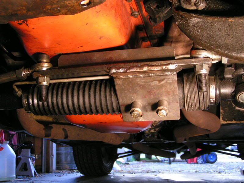
Thought I would chime in here as I just went through this on my 69 Vette. The old Corvettes came with a balky power steering system that uses a hydraulic ram attached to a drank link, all powered by a separate control valve. Anyways, many of us are converting to a "modern" rack and pinion. A kit is available, but the cost is high. I made my own using a rack I found on ebay. They key to this, and why I bring it up, is that the rack I used is a center take off rack. This means you can make a bracket that bolts to the rack and get your tie rods to be any length you want. That is one of the biggest keys to eliminating bumpsteer. See the pics below.

I measured my bumpsteer with a simple homemade device. I took the springs out and raised and lowered the car with a floor jack. I then weighted two jackstands down so they couldn't move. I placed a piece of 1.25" square tubing across the jackstands. Finally, I measured from the tubing to the rim, front and back, to determine the bump. As mentioned before, you need to leave room for the track width changes that are built into the system. I simply subtracted the measurement at the front from the back to get the actual toe. Also, not only is a low amount of bump important, but the direction of the bump. If the bump steer is causing toe out, your car will be darty. If anything, you want toe in.

Ken

PICT0787.jpg
 
In Richard's post earlier he had part of an article about rack lenght. It mentioned finding the cars "instant center" in determining where the rack should be. I am curious as to how to go about finding that point. Is that a theoretical or real point?
Then in his article it said it was based on a line from the lower to upper pivot points. I was then concerned as to where that line is drawn as the suspension of the Corvette is not a box layout. The upper pivot points are in a different plane, and travel through a different arc. This is why i need a better idea of where the rack is placed. Not only up and down, but front and back. Onced located, it is a matter of shimming to get the system right. This is also why this is such a dark sicience to me. I am pretty good with math and geometry, but never having experienced the real world of "the science", is why I raised the question in the first place. I know from looking at the old RHD rack that came with the car, that the height of the new rack would be higher. The original rack pivot points are narrower than the Flaming River unit.
All these discussions are great, once I get the rack mounted, and I will surely pass them on to the people who are going to set up the front end once the rack is in place. The corvette guys won't be any help as their horizontal measurements will be different from mine, and their rack pivot points will also be different.
So as Richard and Jack point out, none of this will be relative til the rack is mounted. One hole (slightly enlarged) will be better than 2 far apart. I appreciate everyones help and info so far. Keep it comming, as it will be used later on by me, and I am sure some can use it now. I have supplied Jack with all of the measurements of the suspension and rack. He should have some "numbers" for me shortly which I will pass along for others in my predicament. I guess I could have avoided it all by contacting Peter and bought one of their reconditioned units and been done with it. Shipping and all would have probably cost about the same. I may be wrong, but I don't think the LHD units they furnish are quick ratios(which mine is). At any rate, I have the FR unit and I need to make it work. Had I thought bump steer would be a problem while the panels were off, it would have been a much simpler task. Thanks for the info guys, and keep it comming. Maybe I will pick up some points that will help in the future.

Bill
 
Hey Bill
I mapped the front Bumpsteer on my DRB on the wheel aligner at work with unmodified DRB front end.
As you can see it is pretty terrible. We are looking at using a kit
from Ecklers which basically drops the outer tierod down 50mm or so as this
is what is required to fix this problem (instead of raising rack). This kit is designed to fix bumpsteer issues on C4's.
 

Attachments

  • SuspensionFrontBumpsteer.JPG
    SuspensionFrontBumpsteer.JPG
    22.6 KB · Views: 588
Last edited:
There are several suspension geometry design/analysis packages out there that can let you analyze without cutting metal. You need to know all of the data (3-D pickup points, etc.). Example is "Susprog3d."
 
The front to back placement of the rack will not affect the bump steer. Bump steer is caused by the pivot points of the tie rod not being in line with the upper and lower a-arm pivots. It's hard to describe without a picture, so take a look at this thread. Post #13 has a great pic of a short-long arm suspension and how to find the instant center, and how to position your rack correctly.

My Rack Conversion - Corvette Forum

As you can see, you can adjust bump steer by moving the pivot points up and down, or by changing the length of the tie rod.

Hope this helps.

Ken
 
.. and just to add my 10 Rubles to the discussion. I used several methods of measuring bump steer after the design of my lambo chassis from scratch.
Everything that has been said above about the positioning right. I first read all the books I could on the subject and talked to everyone supposedly 'in the know' then drew my own conclusions after filtering out the crap!
Anyway, I used the laser pointer idea too. Except I put the pointer facing toward the 'side' of the car, instead of forward. This was projected onto a graphed peice of wood so I could see how the wheel was performing. I also used the dual dial-gauges method as well. I found both methods great when seeing the fruits of my handywork. I was able to determine that after my 2D paper design and string lines in my lounge, that my bump steer was almost non-existant with careful planning and setup. (and late nights, spoiled mounts and whining girlfriends)
 
Hi all,
The C4 corvette uprights that Bill is using, does any body know the King Pin Inclination of them. I am thinking of using them, so any personal feed back would be great good or bad.

Rohan
 

Russ Noble

GT40s Supporter
Lifetime Supporter
RamboLambo said:
Anyway, I used the laser pointer idea too. Except I put the pointer facing toward the 'side' of the car, instead of forward. This was projected onto a graphed peice of wood so I could see how the wheel was performing.

RamboLambo,

An brilliant refinement of the laser application. I wil remember that.

Thanks.
 
Russ Noble said:
RamboLambo,

An brilliant refinement of the laser application. I wil remember that.

Thanks.

Agreed, in a 'zero bump steer' setup, if the laser was fixed as in my diagram, it would track a slight curve, due to the track change.

With the laser pointing outwards, it would track a perfectly straight line.

A brilliant idea indeed!
 
rohan said:
Hi all,
The C4 corvette uprights that Bill is using, does any body know the King Pin Inclination of them. I am thinking of using them, so any personal feed back would be great good or bad.

Rohan

I measured up points of a car for Bills info, Using the rear face of the brake rotor as a reference plane the top ball joint instant center is 1.600" further from the rotor face than the lower ball joint ( Top/Bottom ball joint instant centers were 12" apart in this case) You should be able to draw two divergent lines with those measurement to obtain the angle from.

Jac Mac
 
Julian West said:
Agreed, in a 'zero bump steer' setup, if the laser was fixed as in my diagram, it would track a slight curve, due to the track change.

With the laser pointing outwards, it would track a perfectly straight line.

A brilliant idea indeed!

This is not true in most cases. The upper a-arm is ofter inclined to offer some anti-dive characteristics. The lower arm is inclined for some cars, like the Viper. The chances that both upper and lower a-arm pivots are parallel, is probably small, unless you design it that way. If you do, it will lead to increased nose dive under braking. This may or may not matter depending on your spring rates.

Ken
 

Russ Noble

GT40s Supporter
Lifetime Supporter
BB69 said:
This is not true in most cases. The upper a-arm is ofter inclined to offer some anti-dive characteristics. The lower arm is inclined for some cars, like the Viper. The chances that both upper and lower a-arm pivots are parallel, is probably small, unless you design it that way. If you do, it will lead to increased nose dive under braking. This may or may not matter depending on your spring rates.

Ken

Whilst this is true, IMHO the effect of anti dive would be negligible particularly if the laser was beamed to a board set some distance from the car.

Perhaps the old racing "string line" method still takes a lot of beating for simplicity and practicality. Probably not hi tech enough for a lot of the folks here though. You can't get the measurements to five decimal places! Still works though.

Cheers
 
jac mac said:
I measured up points of a car for Bills info, Using the rear face of the brake rotor as a reference plane the top ball joint instant center is 1.600" further from the rotor face than the lower ball joint ( Top/Bottom ball joint instant centers were 12" apart in this case) You should be able to draw two divergent lines with those measurement to obtain the angle from.

Jac Mac


Many thanks Jac Mac.


Rohan
 
IMHO when it comes to measuring bumpsteer you need to do
it on a wheel alignment machine, it takes into account all possible changes
to geometry and just gives you the true toe readings. Bouncing my DRB up and down at home with crude pointers and the like seemed like I had zero or near zero bumpsteer. But as soon as I put it on the aligner the sad truth prevailed.
 
Well I have done the template(jig) method of measuring the amount of bump steer in my front end. I realise that this is only close, but that is all I wanted in the first place. I didn't want to cut a hole to far from the end point, and then have to cut again and attemp a repair. As it is, with the panelling in place, I will have to cut a bigger hole than I wanted because the entire rack is miles longer than the width of the panels. So the mounting part of the rack will have to be passed through the hole so that the other side can slide into its hole. So the right placement is even more important. I built a jig from flat stock and bent the outside piece so that it would line up with where the rack would wind up in the vertical plane. I then attempted to pop holes evey 1/2" and then put it through its paces to see where all the points ould line up on the horizontal laser method. As you can see I used my vewry best JERRYRIGGING to get as close to the actual movement as possible. Points to note. The 5th measurement is = to the lower A arm being in the horizontal plane. The measurement that best lined up for no bump steer was about 3.75" above the mounting bolt of the lower A arm.(remember I popped these holes with a plasma tourch and then drilled them out) This puts it at the top of the stock rack mount, which will now have to be altered. Its stock mounting hole was only 2" above that point. As you can see in the graph, that is horribly off. At seast with my rack that is. My rack has the fulcrum point 1 1/2" outside the lower A arm mounting bolts. So it was a guess as to where that magic line is that connects the tow pivot points. In the measurements that I supplied to Jack, I realized that they were way off when he sent me the solution to the bump steer. I knew I had measured wrong when he mentioned the upper A arm mounts were 3.75" further out from the lowers. I immediately knew that couldn't be and remeasured. Sure enough I was way off on my measurements. So I decided to go the manual route. I will use his formulas to see if they come out to the same numbers I got.
My laser pointer was actually a laser line level. Because they use a reflector to get the line, I blocked off a part of the beam and voila, you get a point. I then used a carpenters level to keep the wheel from rotating during the measurements(would throw off the points), and hold the laser. It took me most of the day to get these points as things would not reproduce. then I discovered that certain pieces would move. So they had to be secured.
I think what is gotten most out of this exercise is that, a small amount of change in the rack position really affects the bump steer. I am curious if there is anyone who has used one of the bump steer correction pieces that raises or lowers the steering arm alone. I don't see how this would really correct the situation. Maybe someone more engineered than myself could enlighten us.

Bill
 

Attachments

  • P1010280 (Small).JPG
    P1010280 (Small).JPG
    76.6 KB · Views: 372
  • P1010281 (Small).JPG
    P1010281 (Small).JPG
    66.6 KB · Views: 380
  • P1010284 (Small).JPG
    P1010284 (Small).JPG
    66.4 KB · Views: 379
  • P1010283 (Small).JPG
    P1010283 (Small).JPG
    40.5 KB · Views: 411
Back
Top