chris gt40

Dave Bilyk

Dave Bilyk
Supporter
Very nice
Chris, I didn't know about that, I have a reusable one but without the inserts, next time -. I guess it would also prevent having to go round and round and round the tightening sequence too!
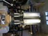
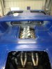
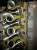
I like the 4 bolt mains too, I wonder if a standard block can be converted?

Dave
 
hello everyone got a bit more done over weekend
gearbox mounts/air con /shifter selector had to clearance
around belly pan for gearbox just keep nocking jobs down
one at a time the more you finish the more there seems to
be to be done
chris
 

Attachments

  • IMG_0661.JPG
    IMG_0661.JPG
    187.7 KB · Views: 725
  • IMG_0662.JPG
    IMG_0662.JPG
    170.4 KB · Views: 634
  • IMG_0671.JPG
    IMG_0671.JPG
    177.6 KB · Views: 735
  • IMG_0672.JPG
    IMG_0672.JPG
    182.7 KB · Views: 688
  • IMG_0673.JPG
    IMG_0673.JPG
    186 KB · Views: 742
hello a small update fitted a nrg quick release and steering wheel
really like the system no play in any direction also have been working on
intake and have a couple of questions if anyone could help that would
be great
can you buy longer reach f/injectors?
does it matter if f/injectors are at right angle to bore?
is the runner length critical or do you get a happy medium
it is about 280 mm from trumpett inlet to center of valve?
manifold is just out of craft wood at the moment before i
butcher any alloy open to any suggestions or mods i know it is
a bit rough
chris
 

Attachments

  • IMG_0720.JPG
    IMG_0720.JPG
    166.5 KB · Views: 630
  • IMG_0730.JPG
    IMG_0730.JPG
    177.3 KB · Views: 630
  • IMG_0732.JPG
    IMG_0732.JPG
    161.3 KB · Views: 639
  • IMG_0733.JPG
    IMG_0733.JPG
    194.7 KB · Views: 641
  • IMG_0734.JPG
    IMG_0734.JPG
    161.5 KB · Views: 568

Keith

Moderator
That certainly is an unusual intake Chris! Is that your own design? I think the runner length and injector position is extremely important to engine use/performance/rev range, but I have no data. Somebody here will for sure though....

Looks an interesting build mate.. :thumbsup:
 
Hi Chris,

Some excellent work & thought going into your build. I do like the start of your inlet manifold.

The spray pattern of an injector is that of a cone and the aim is to position the injector so that it centrally targets the back of the inlet valve. This maximises fuel vapourisation, which is what you want to give you good combustion and clean emissions. Fuel hitting the inlet tract wall will result in ‘wall wetting’ and leads to un-burnt hydrocarbons. There are also normally placed between the valve and the throttle blade, again it not good for emissions to fire the injector onto a partially closed throttle valve.

Well that’s the theory. I wouldn’t recommend what you’ve currently got mocked up, they do need to be facing down the port, other wise you’ll have problems calibrating it for good idle emissions.
Regards,
Andy
 

Randy V

Moderator-Admin
Staff member
Admin
Lifetime Supporter
I agree with Andy on this.

While it will be more work, I would look into coming in from the opposite side of the throttle body with a greater angle. You may have to create a long tunnel for the fuel mixture to be sprayed through to accomplish that. As long as that tunnel were somewhat cone shaped itself to allow the fuel spray to make it into the air stream before it's deflected I think you'd be fine.

Your setup looks nice. Rather unique!
 
It will be difficult to get an ideal inj position.
The current location will give port weting and poor drivability at lower RPM.
It may exhibit blowing of black smoke due to the wetting.
This can lead to bore washing

If a better location cannot be achieved at the port, installation in the entry of the trumpet would be an option or in the side of the trumpet above the butterfly.
Any standoff can be reduced by inj timing.
If your ECU is capable you can change the timing at different rpm to maximize power and emissions.

I think ideal for the location you have would be vertical or the top of the inj leaning into the valley more.
It looks a long way of from that at the moment.

Heads made for inj are easier because the manufacturers put a relief in the port for the nozzle to live in, these heads are still living on carbys and the runner is designed for that so anything maybe a compromise

Ranndys suggestion would work if you can package a fuel rail in the space, you have 2 looking at the space that maybe hard.

Nothing is easy Chris,but you already know that.

Jim
 
thanks keith/andy/randy and jim i have filled and can redrill injector locations at 45 degrees to runner possibly more wich will give me a
clearer shot at the back of valve in doing so this means the tip of
the injector may not intrude into runner but if i underatand what i
am hearing as it injects fuel in a cone shape perhaps the first 5 to 10 mm
of delivery wont be that wide or does the injector have to protrude a certian amount into port runner these may seem like dumb questions but
i am not a mechanic just a plumber so all help is appreciated will post photo of altered injector locations hopefully tomorrow thanks again everone
chris
 
The inj projecting into the port is fine as it stops the spray pattern hitting the top of the port.
If is out of the port it will atomize onto the inside of the inj boss.
If you have not got inj yet Chris you should ring .
Their is inj and their is injectors.

Jim
 
hello again i have been able to relocate injectors at a more suitable
angle to throttle bore for better shot at valve also diagram of injector
position relative to bore does this look better
 

Attachments

  • IMG_0742.JPG
    IMG_0742.JPG
    110.5 KB · Views: 593
  • IMG_0745.JPG
    IMG_0745.JPG
    144.2 KB · Views: 509
  • IMG_0747.JPG
    IMG_0747.JPG
    241.4 KB · Views: 520
  • IMG_0750.JPG
    IMG_0750.JPG
    196.9 KB · Views: 587
hello everyone shortend up axles today machined down then press
fit sleeve over and weld up also trial fitted the rear vents much
better than i had allready done waiting on alloy for manifold and
s/steel bends for exhaust seem to be in workshop a lot but not
much progress
chris
 

Attachments

  • IMG_0792.JPG
    IMG_0792.JPG
    196.1 KB · Views: 652
  • IMG_0793.JPG
    IMG_0793.JPG
    186.5 KB · Views: 654
  • IMG_0795.JPG
    IMG_0795.JPG
    184.5 KB · Views: 638
  • IMG_0797.JPG
    IMG_0797.JPG
    178.9 KB · Views: 639
  • IMG_0801.JPG
    IMG_0801.JPG
    161.5 KB · Views: 615
Hi Chris,
Great looking vents, as fitted to the best cars, glad you liked them :thumbsup:

On a separate note, regarding your fabricated rear uprights, I believe that as shown in your build log, they don’t look stiff enough and could lead to rear wheel steer and potential fatigue failure. This is not only my concern, but also a couple of colleges who are our chassis designers (Lotus Engineering). The suggestion is that the open box sections are closed off, which will stop them twisting under load. Also a brace fitted between the two lower ones will transfer fore/aft loads in the rearward leg. Adding the two plates as show (sorry for crap drawing, it needs to be ideally welded to the bearing housing as well for maximum stiffness) should do the trick
Regards,
Andy
 

Attachments

  • Modified rear uprights.jpg
    Modified rear uprights.jpg
    114.8 KB · Views: 710
hello everyone had a go at making mufflers
started with some 2.5mm perf tube 2.5 mm cats
some sheet s/steel i have 800mm of perf in the mufflers
packed with fiberglass hope the photos help to explain
still have to make a heat shield but happy so far
chris
 

Attachments

  • IMG_0841.JPG
    IMG_0841.JPG
    169.1 KB · Views: 529
  • IMG_0834.JPG
    IMG_0834.JPG
    163.3 KB · Views: 509
  • IMG_0835.JPG
    IMG_0835.JPG
    164.8 KB · Views: 522
  • IMG_0842.JPG
    IMG_0842.JPG
    169 KB · Views: 531
  • IMG_0860.JPG
    IMG_0860.JPG
    149.9 KB · Views: 502
  • IMG_0856.JPG
    IMG_0856.JPG
    138.2 KB · Views: 455
  • IMG_0857.JPG
    IMG_0857.JPG
    126.8 KB · Views: 509
  • IMG_0858.JPG
    IMG_0858.JPG
    177.7 KB · Views: 461
  • IMG_0859.JPG
    IMG_0859.JPG
    161.7 KB · Views: 554
  • IMG_0863.JPG
    IMG_0863.JPG
    168.6 KB · Views: 506
Back
Top