Chuck and Ryan's RCR Build

Chuck

Supporter
Door Details

1. Since we have a roll cage, a hole was cut on the front inner liner to provide adequate clearance. We did not like that ugly hole, so it was glassed with two layers on the inside and then filler was used to provide a nice smooth surface for paint.

2. Nothing was done to the openings on the inside panel. We plan to cut out inserts and cover them to match the leather seats. A small storage compartment may be fabricated for the forward opening. More details will be coming.
 

Attachments

  • FillerDoor.JPG
    FillerDoor.JPG
    130.6 KB · Views: 802

Chuck

Supporter
Rear Clip Details

1. The lip around the upper portion of the wheel openings was trimmed back to assure adequate tire clearance. It is a bit close. Cheap insurance, and easier now than after it is painted. The cut line was marked with blue vinyl tape as shown in the picture.

2. A section of fiberglass cloth, 16” x 4”, was placed on the inside above the wheel opening. It made it noticeably stiffer, compensating for trimming the lip. The area is outlined with a black sharpie in the picture.

3. A section of fiberglass cloth, 20” x 8”, was placed on the inside of the clip just aft of the top vent opening. That area had a fair amount of flex, which is not likely a problem, but the addition of that fiberglass stiffened it up a bit. The area is outlined in the picture.

4. Openings were cut in the forward portion of the clip liner to clear the expansion tank and the fuel pump fittings. They will not be closed off, but the bare fiberglass inside will be painted black.

5. An aluminum plate will be fabricated to hold the license plate and the license plate lights. It will be secured with four screws. Since it is nearly impossible to get in behind to secure a nut, four Nutserts were placed at strategic locations. Two more holes, corresponding to the upper holes on the license plate were drilled, just in case we get lazy and decide to screw the license plate directly to the body until a proper plate hanger is made. Regardless, we plan to space the plate out with nylon washers at least a half inch to enhance air flow from the duct.
 

Attachments

  • RearClipTrimTire.JPG
    RearClipTrimTire.JPG
    147.7 KB · Views: 772
  • FillerRearClip1.JPG
    FillerRearClip1.JPG
    112.2 KB · Views: 692
  • FillerRearClip2.JPG
    FillerRearClip2.JPG
    129.7 KB · Views: 681
  • LicenseBracket1.JPG
    LicenseBracket1.JPG
    103.9 KB · Views: 733

Chuck

Supporter
Cutting the Plexi Glass Windows and Light Covers

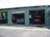
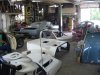
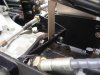
While waiting for our trailer to arrive so we could transport the car to the painter, several additional jobs were completed, like fitting the glass. In retrospect, doing this before painting is a really good idea. Scratching the paint would be hard to avoid. Fitting the side windows was accomplished as follows:

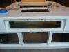
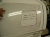
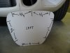
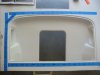
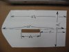
1. Make a pattern for the door glass The pattern was not used for fitting the windows, per se, but rather to assure that the small opening was located the same distance from the rear and bottom on both sides. Reference marks were then made with the pattern to locate the lower and rear edges.

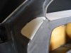
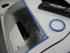
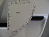
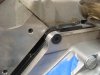
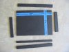
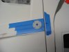
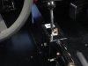
2. Set the plexi glass in place and, using a Sharpie, mark a series of dots along the bottom and rear edge to approximate the edge of the opening. Then use Scotch vinyl tape to mark the cut lines, about a sixteenth inch larger than the final dimension.

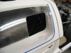
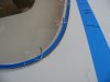
3. Cut the rear and lower portions along the vinyl tape. Test fit it. Using a long sanding block with 40 grit paper or a rasp to even the edges until a good fit of the rear and lower edges is achieved. Do not cut all four edges at one time. Initially cut only the rear and lower edges. This is important. If one tries to cut out all four sides at one time there will likely be problems with the final fit.

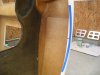
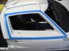
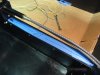
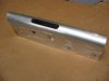
4. Once a reasonably good fit of the rear and lower edges is accomplished, make a series of dots for the top and leading edges, than run the vinyl tape to mark the cut line. Cut only the top edge, slightly oversized, and then sand it down to an exact fit.

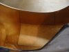
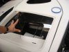
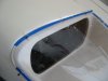
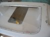
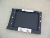
5. Next cut the forward edge, a bit over size, and sand it down. The plexiglass was set in place, removed, a bit more sanded, repeatedly, until a very good fit was achieved all around.

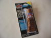
6.Taper the edge inward with fine grit paper. We sanded the edges the final time using fine grit paper in our hand rather than a block. This smoothed the sharp edges a bit

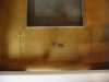
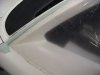
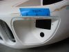
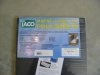
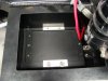
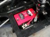
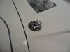
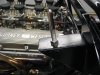
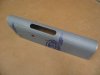
7. The same technique was followed on the headlight and driving light covers.

8. A bit of sanding was needed on the body at the top of the driving light recess to properly seat the plexi glass cover. This discovery was yet another reason to fit the glass before painting the body.
 

Attachments

  • Windows4Pattern.JPG
    Windows4Pattern.JPG
    107.6 KB · Views: 714
  • windows2.JPG
    windows2.JPG
    99.3 KB · Views: 689
  • Windows5.JPG
    Windows5.JPG
    131.1 KB · Views: 722
  • Windows7.JPG
    Windows7.JPG
    121.9 KB · Views: 691
  • Windows8.JPG
    Windows8.JPG
    112.5 KB · Views: 736
  • FillerDrivingLightTrim.JPG
    FillerDrivingLightTrim.JPG
    101.9 KB · Views: 682

Chuck

Supporter
Installing the Plexi Glass Windows and Light Covers

1. The locations for the screw holes were determined. The spacing for the windows is shown in the photo and is based on a prototype car, although one can see significant variation in the number and placement of the screws on different cars. For the headlight and driving light covers a pattern was made and the spacing determined, then transferred to the body. Pencil marks were placed perpendicular to the edge of the opening.

2. Next quarter inch wide blue vinyl tape was applied around the perimeter of the plexi glass panels. The glass was set in place. The points where the pencil line and the tape intersected was the location for the screws holes. This assured that the screws were placed a consistent and even distance from the edge of the glass.

3. Sixteenth inch holes were drilled to assure the exact location through the glass and into the door or body. After each hole was drilled a nail was inserted to keep it aligned. This was repeated until all the holes were drilled followed by larger holes to accommodate the screws. A 5/32” hole was used on the glass to easily clear the 6/32 stainless screws. A tap was used on the fiberglass to make inserting the screws easier. Since minimal force will be exerted upon these screws, they should be secure simply going into the fiberglass.

4. The screws were placed, being careful to avoid making them too tight. A bit of a gap was left to permit expansion and avoid distorting the plexi glass. When we install the glass for the last time after the car is painted, we may put a tiny dab of silicone on the screws to assure they stay put.

5. We polished our windows with Griot’s Plastic Polish. It was helpful in removing the tiny abrasions that happen when working with this material.
 

Attachments

  • WindowGlass1.JPG
    WindowGlass1.JPG
    127.6 KB · Views: 625
  • HeadlightGlass1.JPG
    HeadlightGlass1.JPG
    88.9 KB · Views: 650
  • HeadlightGlass3.JPG
    HeadlightGlass3.JPG
    104 KB · Views: 638
  • HeadlightGlass2.JPG
    HeadlightGlass2.JPG
    100.3 KB · Views: 653
  • GlassGriots.JPG
    GlassGriots.JPG
    105.1 KB · Views: 666

Chuck

Supporter
Installing the Rear Clip Glass

The rear clip glass is a much heavier material than the side windows and light covers. Here is how we installed. It.

1. The edges were trimmed, mostly on the sides, to obtain a good fit. The edges were tapered inward slightly.

2. The location of the holes was determined. We used a Gulf GT as a guide. The spacing of the holes is shown in the photo. Lines perpendicular from the window frame were marked.

3. Quarter inch wide vinyl tape was run along the outer edge. The glass was set in place. Where the inner edge of the blue tape intersected the lines guide holes were drilled and nails inserted to keep it all in place.

4. Next 5/32” holes were drilled through the glass and the body. These holes will accommodate the 6/32 screws with a bit of slack for expansion.

5. The Glass was removed and the fun part of the project started. Since the rear window may need to be removed from time to time, and since its greater weight and size warrant a more secure attachment than simply screwing into fiberglass, we opted to install Nutserts for each hole. This was a slow, time consuming project. Twenty seven (27) Nutserts later the job was done.

6. The glass was polished with Griots Plastic polish. Either Phillips head 6-32 (more authentic) or 6-32 button head screws (neater looking) will be used. Haven't decided yet. Job done, ready for the painter!!!!
 

Attachments

  • GlassRearDimensions.JPG
    GlassRearDimensions.JPG
    103.1 KB · Views: 599
  • GlassRearHoles.JPG
    GlassRearHoles.JPG
    92.1 KB · Views: 589
  • GlassRearComplete.JPG
    GlassRearComplete.JPG
    94 KB · Views: 704

Chuck

Supporter
Body to the painter!

Friday, July 18, 2008, Ryan and delivered the body to Ray Maserang, Walnut Park Auto Body, Crestwood, MO. (St. Louis). We settled on Guardsman Blue. The “FORD” rocker panel stripe will be Wimbeldon white. Both are vintage 60’s Ford colors, used on the Shelby Mustangs in the mid 60’s.

Ray did a super job on his Gulf GT, featured on the cover of Kit Car Magazine after Run &Gun last October.

We have about four or five weeks to finish the chassis details before the body is painted. Our goal: finished and ready for Run &Gun in October.
 

Attachments

  • BodyDelivery3.JPG
    BodyDelivery3.JPG
    190.4 KB · Views: 663
  • BodyDelivery1.JPG
    BodyDelivery1.JPG
    139.8 KB · Views: 649
  • BodyDelivery2.JPG
    BodyDelivery2.JPG
    173.7 KB · Views: 850
Chuck and Ryan,

Fine choice of painters, Ray did a "beautious" job on his car. Yours has been a fine build and inspired me every time I have opened your build pages.

You guys should do the second edition of Fran's build manual! Well done, cruise to the finish line.

Now that you are finishing up and have already done a Cobra, what's next?

Cheers,
Howard

________________________________________________________________
RCR 40 underway
Parnelli Jones 302 as it's garage mate
 

Chuck

Supporter
Dean:

Used a Sears Cutting Tool with a multi purpose / fiberglass cutting bit. Works great, but one needs a steady hand.
 

Attachments

  • CuttingTool.JPG
    CuttingTool.JPG
    177.4 KB · Views: 659

Chuck

Supporter
Exhaust system

There were a couple of minor issues with the exhaust system. One of the bolts securing the adaptor plate to the engine interfered with a pipe on the header. Fran suggested a solution that worked very well. The offending bolt was removed, the hole reamed with a three quarter inch countersink, and a flush hex head bolt installed. This solved the problem

The Weslake Guerny valve covers are thicker than the usual “Ford” covers. One of the header pipes was in direct contact with the valve cover (not a problem with the standard covers). A bit of filing on the Weslake Gureny cover opened up a 1/16th inch gap, solving that problem.

The collectors are secured to headers with four quarter inch stainless bolts, however we did not crank them down tight. Instead a tiny bit of play was left and a second nut added to each bolt to keep them in place. This will minimize any distortion that might occur from variations in the expansion of the metal.

To assure a leak free seal between the collectors and the headers, a bead of high temp Permatex Ultra Copper was run around each collector opening before it was pushed on to the headers. This eliminated the bit daylight that was otherwise visible when looking into the tail pipes.

The muffler supplied by RCR has a single bracket on the bottom which lines up with an unused hole on the Audi transmission. A button head stainless screw was used to secure this bracket. A button head screw was used because a low profile was necessary to avoid interfering with the shifter cable bracket.

A bit of Mother’s Billet Polish really made it shine.
 

Attachments

  • ExhaustBolt.JPG
    ExhaustBolt.JPG
    160.9 KB · Views: 682
  • ExhaustCollectorBolts.JPG
    ExhaustCollectorBolts.JPG
    187.2 KB · Views: 771
  • Exhaust Sealer2.JPG
    Exhaust Sealer2.JPG
    125.5 KB · Views: 582
  • ExhaustMufflerBracket3.JPG
    ExhaustMufflerBracket3.JPG
    142.9 KB · Views: 739
  • ExhaustMuffler.JPG
    ExhaustMuffler.JPG
    189.7 KB · Views: 772

Chuck

Supporter
Battery Tray

The battery was installed in the compartment on the starboard side aft of the fuel tank. A quarter inch sheet of black marine lumbar, some times called Starboard, was used. It is easy to work with and is useful in certain applications, like a battery tray. The tray was designed so that the battery could be secured with a clamp at the base to avoid clamps and braces on the top of the battery.

The attached pictures illustrate how we did it. The tray was designed for a small Optima gel type battery. Note that a half inch wide piece was placed along the bottom of the inner edge to level the tray – the base of the compartment is angled. The pieces were held together with stainless steel screws, all countersunk. Once complete, two quarter inch screws were used to secure the tray to the car. The holes in the chassis were drilled and tapped so they can be removed without having to remove the rocker panel, should that ever be necessary.

Aluminum flat stock was used to make the brackets. The inner bracket is permanent. The outer can be easily removed with the two wing nuts.

The negative cable was secured to the chassis next to the battery and the positive was led through a grommeted hole to the starter. We also drilled a small hole in this compartment to permit any undesirable fluids to drain out.
 

Attachments

  • BatteryTray2.JPG
    BatteryTray2.JPG
    141.7 KB · Views: 486
  • BatteryTray1.JPG
    BatteryTray1.JPG
    125.1 KB · Views: 513
  • BatteryTray3.JPG
    BatteryTray3.JPG
    105.6 KB · Views: 573
  • BatteryTray4.JPG
    BatteryTray4.JPG
    106.9 KB · Views: 487
  • BatteryTray5.JPG
    BatteryTray5.JPG
    152.3 KB · Views: 634
  • BatteryTray7.JPG
    BatteryTray7.JPG
    163.9 KB · Views: 687

Chuck

Supporter
Rear Clip Pins

After a bit of research, a nice stainless steel hood pin kit was found at Branda Performance, Inc., Altoona, PA. (814) 942-1869. Tony Branda specializes in vintage Mustang parts. It is described as a 1965 SH Stainless Hood Pin Kit, Item HPK2. It includes the pins, protective plate, locking pin and nuts. It is a perfect fit on the GT. It is a bit pricey, but the all stainless construction makes it worth the cost.

The location of the center line of the bracket was marked on the spider and used as a reference for centering the hole on the rear clip. The front edge of the protector plate was spaced ¾” aft of the leading edge of the rear clip. A guide hole was drilled, at an angle so it would be perpendicular to the support bracket. Once the suitable location for the holes was established they were drilled out to full size for the pin. The hole on the clip liner had to elongated to about two inches in order to clear the pin as the clip is closed. Once everything was lined up and the holes properly tapered the clip closed without difficulty.

The protector plate was secured with 6-32 stainless button head screws. Nutserts were placed in the clip to hold the button head screws (probably over kill).
 

Attachments

  • HoodPin2.JPG
    HoodPin2.JPG
    90.7 KB · Views: 641
  • HoodPin3.JPG
    HoodPin3.JPG
    82.7 KB · Views: 763
  • HoodPin5.JPG
    HoodPin5.JPG
    156.2 KB · Views: 707

Chuck

Supporter
Shifter

Screw holes in the center tunnel need to be drilled before the coolant hoses and AC tubes are placed.

The rear of the shifter was located 20 inches from the rear of the tunnel. A 1 ½ inch hole was drilled to pass the shifter cables through the fire wall. After drilling the hole we prepared it as we do all holes drilled in the powder coated chassis. We used a fine file to smooth the edges, and then brush painted the exposed aluminum with gloss enamel to protect it and match the powder coating, even though it won’t be seen. Rather than attempt to find a grommet for this hole, we slit a couple of lengths of 3/8” hose and placed it over the shifter cables to prevent any possible abrasion.

We debated about how to secure the gear shifter. Initially we planned to run a 3 ½” screw all the way through. Upon further reflection we decided to use large Nutserts for ¼” button head screws. This proved to be solid and button head stainless screws will result in a clean look, should we elect not to cover the shifter. Two 3/8” nylon spacers were used between the shifter and the tunnel on the driver side only, since the shifter is about ¾” wider than the tunnel. Space is at a premium on the passenger side due to the off center location of the center tunnel, so the center console and gear shifter were kept as flush as possible on the passenger side.
 

Attachments

  • ShifterPlacement.JPG
    ShifterPlacement.JPG
    166.5 KB · Views: 574
  • Shifter3.JPG
    Shifter3.JPG
    111.4 KB · Views: 670

Chuck

Supporter
Center Console Cover

The center console is covered with a simple aluminum cover. We obtained the cover from RCR. A pattern was made to determine the placement of the openings for the brake handle and securing screw holes. To hold it in place three holes were drilled on each side of the tunnel and Nutserts placed. A ¼” gap was left at the back end of the console to provide clearance for insulation and carpeting on the fire wall.

Spacers were placed on the bolts securing the console to the driver’s side. The passenger side was bolted down flush. Two holes were drilled on the passenger side to clear the brake support bracket, which were later covered with the vinyl. Placing the console off center kept it aligned with the shifter and compensated for the narrower space on the passenger side.

After some debate we opted to cover the console with vinyl that matched the vinyl on the sides of the leather seats perfectly. A layer of Cool It thermal insulation was placed over the aluminum. Next the vinyl was cut and glued with contact cement only on the tabs on the back side. Simple, solid, and functional.
 

Attachments

  • ConsoleDimensions.JPG
    ConsoleDimensions.JPG
    94.5 KB · Views: 560
  • Console1.JPG
    Console1.JPG
    110.3 KB · Views: 591
  • ConsoleInsulation.JPG
    ConsoleInsulation.JPG
    107.2 KB · Views: 619
  • ConsoleCenterComplete.JPG
    ConsoleCenterComplete.JPG
    182.2 KB · Views: 885

Chuck

Supporter
Parking Brake

The parking brake handle assembly was installed. We painted the steel bracket low gloss engine black. The aft holes securing it to the chassis were drilled two inches forward of the point where the floor and back panel meet. The bracket was assembled using the upper holes in order to clear the shifter cables.

Note there may be a clearance issue between the seat bottoms and the bolts that hold the brake bracket to the floor. We countersunk one of the bolts on the passenger to address this issue. The other three bolts were not a problem. (See picture).

The best approach is to run the cables and install the calipers first, then locate the brake handle. The cables are pre cut to a specific length and if one installs the handle first an adjustment of the cable length will undoubtedly be necessary. Since we installed the brake handle first, we had this dilemma. In retrospect, the aft hole securing the bracket to the chassis should be approximately three to four inches rather than two inches from the fire wall / rear bulkhead. (See picture). (We put it farther back to avoid any interference with the shifter). This issue was easily resolved, however, by simply adding a one inch long spacer on the cable connected to the handle, effectively shortening the cables by that amount.

We routed the upper shifter cable over the brake bracket. Make sure the cables do not rub on the brake linkage. The shifter looks a bit ungainly once it is in place, but it is a nicely engineered assembly, it is good and solid, and once the aluminum cover is in place it will look like it belongs.

The parking brake cables were installed. Two holes were drilled on the fire wall either side of the shifter cable hole.

The calipers were installed per the RCR instructions. It went together well. This is a nicely engineered assembly that will be seldom used, but I expect it will keep the GT securely stopped when parked.

When securing the cable to the caliper, one can position the “L” bracket either forward or backward. We positioned it backwards for two reasons. First it shortened the cable at the brake handle about an inch, which we needed to do based on where we located the brake handle. Second, locating it in that position tends to push the actuating lever toward the brake pad, which is what one wants. It just seemed right.

Note that the brackets that hold the calipers had an extra bit of steel welded on the end that slides into the caliper. This extra bit of steel should be position away from the brake disc – towards the center line of the car.

The cable needs to be lubricated. One does not want to use ordinary oil since it will gum up the cable over time. We used a chain / cable lubricate, Gunk Liquid Wrench. It worked very well made the cable slide much more smoothly.
 

Attachments

  • EmergencyBrake.JPG
    EmergencyBrake.JPG
    135.5 KB · Views: 592
  • SeatsBoltClearance.JPG
    SeatsBoltClearance.JPG
    135.9 KB · Views: 544
  • EmergencyBrake7.JPG
    EmergencyBrake7.JPG
    157 KB · Views: 706
  • EmergencyBrake10.JPG
    EmergencyBrake10.JPG
    132.7 KB · Views: 598
  • EmergencyBrake8.JPG
    EmergencyBrake8.JPG
    149 KB · Views: 802
  • EmergencyBrake9.JPG
    EmergencyBrake9.JPG
    146.7 KB · Views: 538
Back
Top