
You are using an out of date browser. It may not display this or other websites correctly.
You should upgrade or use an alternative browser.
You should upgrade or use an alternative browser.
Chuck and Ryan's RCR Build
- Thread starter CESLAW
- Start date
Natural, all the way!
Ron McCall
Supporter
I prefer the natural also...
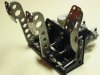
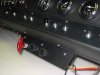
The pedal assembly was a little project that went together well. The pedals were stainless steel, so Ryan spent a bit of time giving them a nice shine with the Scotch Brite pad. The base, which was plain steel, was painted semi gloss engine black which perfectly matches the powder coated chassis.
Upon assembling the pedals a significant amount of lateral play was noted in the brake and gas pedal. A thin piece of brass was cut to size and wrapped around the pivot bolt, eliminating much of the extra slack. When the bolts were tightened the excess slack was gone an all three pedals moved smoothly with minimal side play.
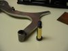
We tapped a hole behind the gas pedal and added a 1 ¼” screw to serve as an adjustable stop screw. The gas pedal has a nice little pad welded on the back side, so this seemed like a logical arrangement.
The kit came with three master cylinders: two were one inch diameter and one was 7/8” diameter. The smaller, 7/8", was used for the clutch and the two once inch cylinders were used for the brakes. I am not sure if this is the correct arrangement. Perhaps someone who has been down this path already with their RCR could give us some feedback?
Upon assembling the pedals a significant amount of lateral play was noted in the brake and gas pedal. A thin piece of brass was cut to size and wrapped around the pivot bolt, eliminating much of the extra slack. When the bolts were tightened the excess slack was gone an all three pedals moved smoothly with minimal side play.
We tapped a hole behind the gas pedal and added a 1 ¼” screw to serve as an adjustable stop screw. The gas pedal has a nice little pad welded on the back side, so this seemed like a logical arrangement.
The kit came with three master cylinders: two were one inch diameter and one was 7/8” diameter. The smaller, 7/8", was used for the clutch and the two once inch cylinders were used for the brakes. I am not sure if this is the correct arrangement. Perhaps someone who has been down this path already with their RCR could give us some feedback?
Attachments
Nice work Chuck & Ryan...
Yes - the smaller master cylinder is for the Clutch. Fran's guys mistakenly packaged 3 1" units in my car, I've returned one and am expecting the exchange unit to arrive.
Nice work on the throttle stop screw - exactly what was in my plans as well.
Any idea on what we are supposed to use for a throttle cable yet?
Randy:
Fran provided me with a throttle cable. I have not studied it yet. I know I am going to have some issues to sort out, particularly securing the cable to the Webers. But that project will be for another day . . . .
Chuck
Oh Fran!!!!!!!!!!!!!!!!!!
Add this to the list I just sent you.....
I didn't get the pulleys you showed either..
Chuck - I just went through doing a cable configuration on my Blown Nova - I'll study your pictures and see if I come up with any ideas..
Thats Tilton not Wilwood...
When specing the RCR caliper/pedal system Wilwood recommended 1 inch M/C'S...
the clutch MC may vary depending upon slave cylinder size for each transaxle variation 7/8 was their catch all solution...
When specing the RCR caliper/pedal system Wilwood recommended 1 inch M/C'S...
the clutch MC may vary depending upon slave cylinder size for each transaxle variation 7/8 was their catch all solution...
Alternator
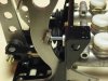
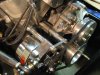
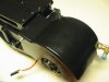
The area for the alternator is tight. Fortunately Rousch makes a nice aluminum bracket, that fits in the space, with about a quarter inch of clearance from the adjacent chassis. A Powermaster GM style one wire alternator ( 100 amp) in polished aluminum, PWM-27294, worked well, with about three quarters of an inch of clearance on the back side.
A crank pulley spacer, Ford Racing part # M-8510-C351, (.950 inch) resulted in a perfect alignment of the crank and water pump pulleys. The water pump pulley bumped against one of the support fins on the water pump, but once an eighth inch of metal was filed away from the pump it cleared with no further drama. We used the pulley supplied with the alternator rather than a larger one, since most of our driving will be cruising, not racing, in the lower RPM range. The project was finished with a 36 inch belt.
Once we receive the bracket for the AC compressor we will install it and the water hoses, thus completing the front of the engine, after which the fire wall will go back in place.
Attachments
Air and Heat, Part I
Two little problems, two easy solutions.
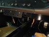
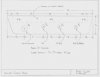
1. There is no provision for adjusting air flow between the side dash vents and the floor vent. There is a lever on the evaporator case which accomplishes that task but it is not accessible once the unit is installed. Realistically, one will not need to be changing the direction of the air flow very often, so cluttering up the dash with another control was not something we wanted to do. It was an easy matter to add a simple cable and knob accessible by reaching under the dash. Simply pulling down directs air to the dash vents, pushing up directs air out the floor vents, and somewhere in between splits the air flow.
2. So what happens if the evaporator needs to be removed once the car is done? Two of the bolts securing the unit are under the fiberglass dash. Removing the dash could be a major headache. By removing only the dash vent access to the two bolts is possible. A couple of holes were drilled inside the vent area, where they will not be seen when the vent grill is in place. This will provide access to the bolts supporting the AC unit, permitting it be removed without having to remove the dashboard. If one plans to direct air out the dash grill, removable plugs could be added to seal these openings.
Two little problems, two easy solutions.
1. There is no provision for adjusting air flow between the side dash vents and the floor vent. There is a lever on the evaporator case which accomplishes that task but it is not accessible once the unit is installed. Realistically, one will not need to be changing the direction of the air flow very often, so cluttering up the dash with another control was not something we wanted to do. It was an easy matter to add a simple cable and knob accessible by reaching under the dash. Simply pulling down directs air to the dash vents, pushing up directs air out the floor vents, and somewhere in between splits the air flow.
2. So what happens if the evaporator needs to be removed once the car is done? Two of the bolts securing the unit are under the fiberglass dash. Removing the dash could be a major headache. By removing only the dash vent access to the two bolts is possible. A couple of holes were drilled inside the vent area, where they will not be seen when the vent grill is in place. This will provide access to the bolts supporting the AC unit, permitting it be removed without having to remove the dashboard. If one plans to direct air out the dash grill, removable plugs could be added to seal these openings.
Attachments
Nicely done....
Great work. Attention to these secondary or tertiary matters now will end up producing a first rate road car. Maintenance issues, removability, and flexibility of adjustment of the air conditioning are very important (road use) and nicely solved here.
Dalton
Dalton
Just to share a little....
I used a 1 inch unit for the back brakes and a 7/8 for the front with a Tilton short 7/8 master for the clutch. The short unit allowed me to move the pedals back quite a bit. I also used banjo fittings to further reduce the space needed for the pedals. I added a toe clip to the accelarator and changed the cable location for a straighter pull.

I wish mine were stainless! That looks great.
I used a 1 inch unit for the back brakes and a 7/8 for the front with a Tilton short 7/8 master for the clutch. The short unit allowed me to move the pedals back quite a bit. I also used banjo fittings to further reduce the space needed for the pedals. I added a toe clip to the accelarator and changed the cable location for a straighter pull.
I wish mine were stainless! That looks great.
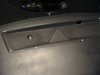
Fitting the Dashboard I
Trimming the dash to fit around the roll bar proved to be a time consuming project. Even taking little nips at a time still resulted in a bit more being removed than we wanted. Fiberglass cloth and resin easily addressed those issues. We added a thin piece of plywood, 1/8” thick, three inches wide and seven inches tall on either side where the dash is secured to the chassis to give more support and make sure that flat surface remained flat. This was then glassed in place with two thicknesses of fiberglass cloth, making for a solid, warp free surface to bolt to the chassis later.
Installing the dashboard with a roll cage is cumbersome. The dash is set in place, after which the roll bar is set in the car. They must be installed together, because of the tight fit for which we opted. Gently lifting the dash a couple of inches – as far as it will go with the roll bar in place, the bolts securing the roll bar can then be inserted. The dash then is lowered into position. This process means that the roll bar cannot be permanently installed until the dashboard is completed, including painted, gauges and switches and wiring installed. More fiberglass could have been cut from the corners of the dash to enable one to set in place with the roll bar already installed, but we opted to keep the fit as tight as possible. Hopefully we won’t later regret the extra effort this requires to install the dash and roll bar.
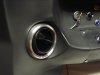
We opted to add the machined aluminum vents from Hot Rod Air, Part 41-0100. These look a bit more original than the plastic vents. A couple of hours of filing both the fiberglass and the aluminum was necessary since the overall diameter of the aluminum vent is a bit larger than the plastic vents, but the hole size is the same.
Trimming the dash to fit around the roll bar proved to be a time consuming project. Even taking little nips at a time still resulted in a bit more being removed than we wanted. Fiberglass cloth and resin easily addressed those issues. We added a thin piece of plywood, 1/8” thick, three inches wide and seven inches tall on either side where the dash is secured to the chassis to give more support and make sure that flat surface remained flat. This was then glassed in place with two thicknesses of fiberglass cloth, making for a solid, warp free surface to bolt to the chassis later.
Installing the dashboard with a roll cage is cumbersome. The dash is set in place, after which the roll bar is set in the car. They must be installed together, because of the tight fit for which we opted. Gently lifting the dash a couple of inches – as far as it will go with the roll bar in place, the bolts securing the roll bar can then be inserted. The dash then is lowered into position. This process means that the roll bar cannot be permanently installed until the dashboard is completed, including painted, gauges and switches and wiring installed. More fiberglass could have been cut from the corners of the dash to enable one to set in place with the roll bar already installed, but we opted to keep the fit as tight as possible. Hopefully we won’t later regret the extra effort this requires to install the dash and roll bar.
We opted to add the machined aluminum vents from Hot Rod Air, Part 41-0100. These look a bit more original than the plastic vents. A couple of hours of filing both the fiberglass and the aluminum was necessary since the overall diameter of the aluminum vent is a bit larger than the plastic vents, but the hole size is the same.
Attachments
Fitting the Dashboard II
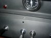
The air conditioning unit has three controls: fan speed, AC temperature, and a cable operated temperature control. We also will be installing a fire suppression system. The original GT had no air conditioning, so we wanted to place the controls in a location other than the switch panels on either side of the dash. A small panel, nine inches wide and two inches tall, was fabricated out of aluminum and secured under the dash, centered below the main switch panel. This ‘biased’ the location towards the passenger side to prevent interference with the driver’s right leg but yet looked appropriate. This extra panel is not obvious, but easily seen and within easy reach from the driver’s seat.
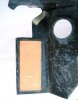
To secure the switch panels and the dash grill Nutserts were used. These are slick little gadgets that make screwing the panels in place a breeze, particularly since the panels are installed and removed many times during the wiring and installation process. We put old screws in them when the dash was painted and primed to avoid gumming up the threads. A picture of a Nutsert is below.
We sanded the dash smooth and sprayed it with primer, sanded again, and then sprayed it with several coats of low gloss engine paint. We were pleased with the results. Next we will install the gauges and move ahead with the wiring.
The air conditioning unit has three controls: fan speed, AC temperature, and a cable operated temperature control. We also will be installing a fire suppression system. The original GT had no air conditioning, so we wanted to place the controls in a location other than the switch panels on either side of the dash. A small panel, nine inches wide and two inches tall, was fabricated out of aluminum and secured under the dash, centered below the main switch panel. This ‘biased’ the location towards the passenger side to prevent interference with the driver’s right leg but yet looked appropriate. This extra panel is not obvious, but easily seen and within easy reach from the driver’s seat.
To secure the switch panels and the dash grill Nutserts were used. These are slick little gadgets that make screwing the panels in place a breeze, particularly since the panels are installed and removed many times during the wiring and installation process. We put old screws in them when the dash was painted and primed to avoid gumming up the threads. A picture of a Nutsert is below.
We sanded the dash smooth and sprayed it with primer, sanded again, and then sprayed it with several coats of low gloss engine paint. We were pleased with the results. Next we will install the gauges and move ahead with the wiring.
Attachments
Last edited:
This is interesting stuff, Chuck. I'm slightly confused (not uncommon these days) by the three air conditioning controls, having TWO temperature controls. One will be sensing the "cold" air temperature and cycling the compressor on and off to maintain the setting. Is the other one to control a hot water valve for heating/demisting?
Very nice work, by the way; well thought out.
Dalton
Very nice work, by the way; well thought out.
Dalton
Similar threads
- Replies
- 0
- Views
- 537
- Replies
- 1
- Views
- 458