Chuck and Ryan's RCR Build

Chuck

Supporter
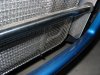
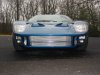
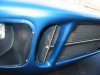
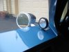
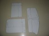
Side Duct Air Deflectors

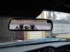
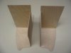
Revising the side air ducts was another item on the B List. As the car sets, one looks inside the ducts and sees the rear tire. Not very original.

The duct should be divided horizontally with most of the air directed to the brakes and the rest directed into the engine compartment. Brake cooling is not really an issue for us, since street use is our primary goal. Directing air into the engine area, however, is important. Moving in slow traffic on a hot day is a good reason to address this issue.

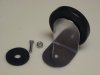
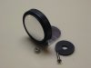
A simple deflector was fabricated with the aid of our usual patterns. Our goal was to (1) direct air into the engine compartment, (2) add the horizontal divider, as seen on the original cars, and (3) block the view of the rear tire one would otherwise see when peering into the vent.

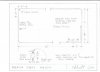
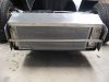
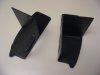
After the patterns were made, sixteenth inch modeler’s plywood was cut to shape. The thin ply was cut to provide a close fit, leaving about an eighth inch from the outer body panel. There is really no need for an airtight seal. All surfaces were then covered with a layer of fiberglass cloth, resulting in a very rigid, strong structure. A coat of engine black, semi gloss, was sprayed and it was ready to install.

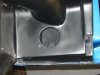
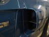
The vents were held in place with two screws and lock nuts on opposite sides of the opening into the engine compartment.

The opening into the engine compartment is a round hole, 3 ¼” inches in diameter. The hole had been drilled before the car was painted.

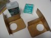
The horizontal divider was finished off with a length of Edge Grip from McMaster- Carr (similar to what is used for weather stripping but without the bulb).

This is a simple approach that adds a touch of authenticity and functionality. If one wants to add brake ducting, it could be easily added by extending the inner panel upward and adding a horizontal top section then adding the opening for the conneting duct.
 

Attachments

  • SideVentPatterns.JPG
    SideVentPatterns.JPG
    81.5 KB · Views: 589
  • SideVentsForms.JPG
    SideVentsForms.JPG
    81.8 KB · Views: 595
  • SideVentFiberglass.JPG
    SideVentFiberglass.JPG
    117.2 KB · Views: 684
  • SideVent2.JPG
    SideVent2.JPG
    81.4 KB · Views: 636
  • SideVent5.JPG
    SideVent5.JPG
    151.2 KB · Views: 670
  • SideVent3.JPG
    SideVent3.JPG
    131 KB · Views: 831

Rob

Lifetime Supporter
Chuck,
As usual....you take the more logical approach.......so rather than hand making your shift knob....you decided to just find one already made, in walnut by the way, with the correct look....that figures. Oh and to top it off, it cost half of what I paid for just the heli-coil, forget about all the work :( Well...I know for next time. Thanks for helping out us slow guys...:thumbsup:

Nice job of the side scoops.
 
Hi There Chuck

Great build i just noticed the collector and Muffler comb on the start of your thread.Can you tell me where you got it ?
Cheers Keo

No worries mate ive just read the whole thread and found the page...I loved the cup holders i might put a pair in my car plus a coffee maker,just wondering if a set of swivel seats might fit..

Great build love the colour
 
Last edited:

Ron McCall

Supporter
Windshield Wiper

The wiper motor supplied with our RCR was a “It’s A Snap” brand. Can’t say I ever heard of that particular manufacturer before, but it is well suited to the GT. Two tips for a successful installation: (1) Lots of grease and (2) A short and direct connection between the motor assembly and the wiper cowl mount.

The cowl mount shaft is just long enough to make a clean, neat installation. After drilling a guide hole in the spider, we continued drilling so we had a corresponding guide hole on the chassis below. The spider was drilled with a 3/8” bit to accommodate the cowl mount shaft. We then drilled a 1 ¼” hole in the chassis to clear the shaft mechanism with plenty of room to move it around for future adjustment. The shaft was long enough so that it came to rest fully below the chassis with a quarter inch to spare.

Finding a location for the motor was easy. Locating the motor forward of the evaporator on the passenger side, secured to the top surface of the chassis, provided a direct, short route for the connecting tube. The four mounting holes were elongated slightly to give some lateral movement for adjustment purposes when the spider is secured in its final position. A double thickness of sound insulation material was placed between the motor and the chassis. (We made our usual pattern before cutting the insulation material, shown in the picture below.) The mounting bracket that came with the wiper kit proved unnecessary.

The aluminum tube was carefully cut to length and the ends flared making a nice, tight fit on both ends. The excess cable was cut off, leaving a couple of inches sticking out on the opposite side of the wiper shaft mechanism. A short section of aluminum tube to protect the free end was added with the necessary flare to keep it in place..

Grease, grease and more grease. The cable was thoroughly greased. The slide guide mechanism was also thoroughly greased.

The final step was to test run the unit to make sure the sweep was appropriate. We removed and replaced the unit a couple of times before finding the right hole on the motor assembly for getting an appropriate arc.

Next we cut a piece of aluminum and expoxied it on the back side of the clip to give a bit more strength to the wiper shaft mechanism. We also drilled the hole for the windshield washer sprayers, adding a 7/8” access hole to the front of the clip for access to the bottom side of the nozzle so that the connecting hose could be added later. A black plastic plug covers these holes.

This part of the project went together well.

Chuck,

Did you use a Lucas 35927 switch for your wipers?? I can get everything to work easily with the switch that was provided with the wiper kit but not with the Lucas switch! Maybe I'm just too stupid.??? Could you let me know which terminals you hooke to on the Lucas switch?? Thanks. (just in case you are wondering....I built my car with no wipers and I had the roof and dash off to install the rest of the roll cage and I figured this was a great time to install the wipers.)
 

Chuck

Supporter
I did use the Lucas 35927. Attached are a couple of pics of the switch. When I got the switches I spent an evening with a volt ohm meter figuring out which terminal did what, then marked them accordingly. In the picture you can see the label, but may not be able to make out the writing. The park terminal is the lower terminal on the rear most portion of the switch.

But here is another thought. I found that the "park" feature parks the wiper up about three inches from its bottom range of travel. It is as if the park feature was intended for a wiper that sweeps in the opposite direction. So I plan to pull that park wire and just shut it off where I want it to stop. When driving around town, park it down. When driving down the Mulsanne Straight at LeMans, part it straight up to minimize the wind resistance. I like having options.

The other picture shows the switches intstalled. On the larger switch panel, the wiper is the third from the right. Hopefully you can make out the wiring.

Here is the info on the wiper switch from my notes:

The GT 40 kit came with an after market (not Lucas) brand wiper motor with a four wire plug. Two wires activate the low and high speed circuits. The other two activate the park function. Using a battery charger as a power source (which is circuit breaker protected and thus preferable to a battery for this purpose) temporary connections were made to determine how the circuits should be wired. Connections were then made to the Lucas wiper switch, 35927. A GM Style plug was then added for ease of servicing or modifications. We are adding a Lucas windshield washer which looks vintage, so its power source was tapped off of the wiper power source as well. (Hard to believe, but one can see Lucas type windshield washers on some vintage photos, hence why not on a reproduction?).

Hope this helps. Good luck.

Chuck
 

Attachments

  • SwitchPanels0907.JPG
    SwitchPanels0907.JPG
    123.8 KB · Views: 536
  • LucasSwitches0407.JPG
    LucasSwitches0407.JPG
    119.2 KB · Views: 483

Chuck

Supporter
After all that jibberish in my last post, look what I found. A specific wiring diagram. Forgot I had drawn it. The terminals on the Lucas switch are numbered, so it should be easy to follow. Hope this helps.

Chuck
 

Attachments

  • DiagramWiperConnections 001.jpg
    DiagramWiperConnections 001.jpg
    23.3 KB · Views: 635

Chuck

Supporter
Radiator Screen

Original GTs typically had a wire screen in front of the radiator, spaced about a half inch away to protect against errant debris. This little detail is particularly useful on the RCR GT to make the AC plumbing less noticeable from the front. We decided to duplicate this piece using stainless steel screen; admittedly not original, but it looks slick. We did, owever, seek to duplicate the original in overall shape and construction.

A wire frame was made from 3/16” plated steel, in four sections. The joints were connected with five inch lengths of aluminum tubing, 7/32” diameter, which has in inside diameter that slides snuggly over the steel frame. The corners were bent with a 1 ¼ inch radius. There was no need to weld or otherwise secure it since the screen will hold it tight. The screen is stainless, coarse mesh, with a quarter inch spacing. We obtained it from Pegasus Auto Racing Supplies. http://www.pegasusautoracing.com/group.asp?GroupID=SCREEN. The screen was cut about an inch larger than the frame, several strands removed around the perimeter, than the wire was carefully bent over the frame, all in the same direction. When finished, the front looks neat and trim.

We sought an easy way to secure the screen to the car. The original screens appeared to have a metal clip wrapped around the frame is four locations, two top and two bottom. Not wanting to cut away any of the screen from the frame, wire ties were used instead. To space the frame away from the radiator, 3/8” I.D. hose, about a half inch long was used. The wire tie was passed through the hose, then looped through a hole in the radiator frame, then back through the hose, and around the screen frame. It was tightened securely, compressing the hose a bit. The result was inconspicuous supports that hold the screen solidly in place but can be easily removed should that be necessary.
 

Attachments

  • Screen6.JPG
    Screen6.JPG
    203.4 KB · Views: 784
  • Jan09Front.JPG
    Jan09Front.JPG
    205 KB · Views: 807

Chuck

Supporter
Attached is a diagram of the radiator screen frame
 

Attachments

  • DiagramRadiatorScreen 001.jpg
    DiagramRadiatorScreen 001.jpg
    28.1 KB · Views: 617
  • RADIATOR SCREEN RCR-GT40.PDF
    301.4 KB · Views: 399

Rob

Lifetime Supporter
Excellent Chuck.
How did you do the cross bar? Would like to know more about that. It looks great. I don't remember reading anything about it......did I miss this post? Yes, you are required to post about "everything"! It is in the fine print of the forum "build log" rules and requirements......
 

Keith

Lifetime Supporter
Chuck,
Once again that is just "over the top". You and Ryan continue to make the rest of us look like amatures............ and makes me have to continue to add to the list things that I just have to copy.
Keith
 

Chuck

Supporter
Tow Bar

Nearly every original GT had a horizontal tow bar in the front radiator opening, located approximately centered top to bottom. Usually it was black steel, although occasionally some daring racers painted it a bright color. We wanted to add this detail. But instead of black, we opted for shinny stainless steel, to add some bling to the front end.

Eighth inch thick aluminum plates were cut to size and mounted on either side of the radiator, using the same bolts that hold the radiator. Rubber spacers were used. The tow bar was cut from one inch polished stainless steel obtained from West Marine. The bar was secured to the plates with ¾” well bolts. Obviously this tow bar is cosmetic, not functional.

So, Rob, you caught me. Thought I had already posted this one.
 

Attachments

  • Towbar1.JPG
    Towbar1.JPG
    136 KB · Views: 691
  • Towbarbracket.JPG
    Towbarbracket.JPG
    102.2 KB · Views: 543
  • Towbar.JPG
    Towbar.JPG
    152.3 KB · Views: 672

Chuck

Supporter
Bits and Pieces

We replaced the fire engine red distributor cap on the small MSD distributor with something a bit more subtle. MSD makes a black one: PN 8750. The matching rotor, for future reference, is PN 8467.

We also learned that MSD makes a shielded distributor pickup wire to reduce the risk of a stray current upsetting the ignition. PN 8862. The shield is grounded at one end. This may be particularly useful if this wire is run alongside other wires, although it did not seem to make a difference when we replaced our non shielded wire. But it is cheap insurance, just in case.

We wanted to dress up the steering wheel hub. A Grant horn button, GRT-5875, available from Summit, fits perfectly on the RCR steering wheel. We replaced the bolts with smaller ones and added nuts to the back side to secure them. One can use the supplied FORD button, using a section of foam tape to secure it in back. Better yet, find someone that makes an original style GT 40 insert, as we did.
 

Attachments

  • DistributorCapBlack.JPG
    DistributorCapBlack.JPG
    195 KB · Views: 851
  • SteeringWheel3.JPG
    SteeringWheel3.JPG
    173.7 KB · Views: 896

Rob

Lifetime Supporter
Looking great Chuck.
Oh... you may want to ditch those venturi socks. They made my engine run rich and lost 25 HP when they were installed. Obviously you could lean out to match....by .... why...
 

Chuck

Supporter
Looking great Chuck.
Oh... you may want to ditch those venturi socks. They made my engine run rich and lost 25 HP when they were installed. Obviously you could lean out to match....by .... why...

Rob: good idea. I like the stainless mesh covers you used. Do they have any noticeable adverse affect on the carb? Noticed that Pierce Manifolds sells them for the IDF carbs

Weber Carburetors, Conversion Kits - Pierce Manifolds Inc.


When we run the car we pull the socks anyway.
 

Rob

Lifetime Supporter
Damn Chuck....how do you do it. You are the king of finding stuff. Yep, I'd say those would work just fine. I didn't see pricing on them, please let us know how much they are once you find out.

Regarding performance, they flow significantly better than the socks. I don't remember the numbers, but they flowed ~ 2.5 x better than the socks. So it was significant. wrt the screens, I had intended to do a pull with the screens off, but forgot to do so. I imagine they are costing a few ponies for sure...but I just don't like running w/o anything to catch at least the big bits.
 

Chuck

Supporter
Good reflections

Few will dispute that the rearward visibility in the GT leaves something to be desired: specifically visibility.

Original GTs typically mounted the outside mirrors on the front clip, either just aft of the fuel filler or forward on the fender. These locations seem to be just about worthless. The “A” pillar obscures the mirror when mounted aft of the fuel filler and the image is just too small when mounted forward on the fender.

We found pictures of original GTs that mounted the mirrors on the doors in John Allen's book, The Ford That Beat Ferrari. This is a much more useful location. There is a ‘sweet spot’ where the surface is flat and straight enough to get it well positioned. The mirrors supplied with the RCR are sturdy reproductions of original style Talbot mirrors. We decided to use them.

Still the field of vision with the side mirrors is compromised. So we added another set of mirrors. While visiting the Carroll Shelby Museum in Boulder, Colorado, we noted that the one of the GT’s had small spot mirrors mounted on the inside of the door. Small spot mirrors with convex lenses are readily available in different sizes from car parts stores which work well. So a bracket was fabricated from a section of two inch aluminum angle stock. The bracket can be secured with a single screw.

A mirror was mounted on the windshield. The original cars moved the mirrors off center toward the passenger side but since our car will see a lot of road use likely with passengers from time to time we mounted it dead center. The original mirror was all metal and thus silver color on the back side, but an inexpensive mirror from a car parts store has the right size and shape and the fact it is not original should not be noticed by most observers. The inside mirror provides a good view of the Webers, but not a whole lot more
 

Attachments

  • MirrorOutside1.JPG
    MirrorOutside1.JPG
    129.5 KB · Views: 659
  • MirrorInside2.JPG
    MirrorInside2.JPG
    116.6 KB · Views: 609
  • MirrorSpot1.JPG
    MirrorSpot1.JPG
    85.6 KB · Views: 566
  • MirorSpot2.JPG
    MirorSpot2.JPG
    78.1 KB · Views: 521
  • MirrorSpot3.JPG
    MirrorSpot3.JPG
    116.7 KB · Views: 768

Ron McCall

Supporter
Chuck,
I have almost the exact same spot mirror on my car. Works great.
Do you have any pictures of the full car with the chrome mirrors on the doors?
 
Back
Top