Chuck and Ryan's RCR Build

Chuck

Supporter
Door Strikers

Some minor modifications were made to the door strikers. The aluminum plates provided by RCR were trimmed and polished. Then supporting brackets were fabricated out of aluminum to provide the appropriate space and angle. The supporting brackets were located under the carpet (the insulation was cut away on the back side of the carpet) to provide a nice flush look. One can still get a wrench behind the striker plate to adjust the striker bolt.

96% Done!
 

Attachments

  • DoorStrikerB.JPG
    DoorStrikerB.JPG
    75.3 KB · Views: 632
  • DoorStrikerA.JPG
    DoorStrikerA.JPG
    85.3 KB · Views: 660
  • DoorStrikerD.JPG
    DoorStrikerD.JPG
    117.5 KB · Views: 789

Keith

Lifetime Supporter
Very nice, I have been thinking about that for several months and had not thought of a way to make the door striker look finished. The large fasteners look great.
Keith
 
Congratulations, You have done a great job on a great product.
Realy feel sad that i will miss R&G and your company

TOM
 
Last edited:

Chuck

Supporter
ChucK. Good color scheme and nice pic. You obviously are a man of good taste.

Tom: Run and Gun less than a week away. So much to do . . . . so little time.
 

Chuck

Supporter
Door Stops

An inconspicuous way of limiting the door travel was needed to prevent the leading edges of the doors being damaged when opened all the way. We also wanted a door stop that would have some flex to prevent stressing the fiberglass door.

A sixteenth inch cable, twelve inches long, was covered with seven inches of clear plastic tubing. A small hole was drilled in the chassis. A double cable stop was put on one end and the cable passed through the hole in the chassis..

A stiff one inch long spring provides a bit of flex as the cable reaches the end of its travel. A five inch long section of eighth inch thick aluminum was drilled and tapped and secured to the back side of the door with two 8-32 screws. A cable stop holds it in place. It can be easily adjusted to vary the distance the door opens..

The plastic cover prevents the cable from scratching anything. When the doors are closed, the cable folds up nicely. When open, it is inconspicuous.

97% Done!!
 

Attachments

  • DoorStop2.JPG
    DoorStop2.JPG
    98.6 KB · Views: 587
  • DoorStop3.JPG
    DoorStop3.JPG
    73.5 KB · Views: 619
  • DoorStop4.JPG
    DoorStop4.JPG
    125.6 KB · Views: 754

Chuck

Supporter
Details, oil pressure warning light

The four warning lights on the dash include two amber turn signals, a blue high beam indicator, and a red light. We were not sure what to do with the red light. It could be wired into the alternator to indicate when it is discharging, but that seemed to be of little benefit since we have a volt meter and an alternator failure is not likely to destroy the engine.. A sudden drop in oil pressure is of much greater consequence, so using the red light as an oil pressure warning seemed like the better use.

An oil pressure warning light kit was purchased, although the only part used was the pressure switch. (It was cheaper to buy the entire kit than just the pressure switch). This particular unit closes the circuit at 20 pounds of pressure.

The sending unit has a single connection and works as a ground switch when the pressure drops below 20 pounds. The red dash light was connected to a 12 volt source switched with the ignition. The other lead from the light was connected to the sending unit. That is all there is to the wiring.

The Canton 5065 remote oil filter bracket has two extra fittings. A couple of adaptors were needed. No Teflon tape was used, since these fittings need to complete the ground circuit.

The Lucas dash light is plenty bright and will likely get ones attention quicker than the oil pressure gauge should there be a sudden drop in pressure.
 

Attachments

  • OilPressLight1.JPG
    OilPressLight1.JPG
    126 KB · Views: 489
  • OilPressLight2.JPG
    OilPressLight2.JPG
    71.1 KB · Views: 486
  • OilPressLight.JPG
    OilPressLight.JPG
    147.1 KB · Views: 630

Chuck

Supporter
Hold down latches

We used the hold down latches provided with the RCR kit, although many opt for other, more original appearing clips. The provided clips are functional and frankly we are not dissatisfied with the look.

A small angle bracket was fabricated from aluminum stock to secure the bottom clip. It was screwed through the fiberglass into the chassis after we drilled and tapped it. This provided an additional point for securing the rocker panels, most useful on the front end. Counter sunk machine screws were used since the clearance is tight. Rivets were used to hold the lower hold down in place.

The fit for the upper portion of the hold down latch within the clip is tight. Fortunately we had test fitted them before the car was painted and had sanded out the opening to provide a bit more clearance.

98% Done!!


Attachments

  • ClipBrackets.JPG
    ClipBrackets.JPG
    124.7 KB · Views: 619
  • Latch.JPG
    Latch.JPG
    130.5 KB · Views: 637
  • ClipClipA.JPG
    ClipClipA.JPG
    124.2 KB · Views: 655
  • ClipClipB.JPG
    ClipClipB.JPG
    121.3 KB · Views: 697

Chuck

Supporter
Spider Final Assembly

A piece of foam weather stripping, 1 ¼ x 7/16”, was placed on the inside top aft end to seal the gap with the rear bulkhead. This is not a perfect seal but does substantially close the gap. The fit is tight around the sides. The flange along the top rear also helps the seal. Once we get the car on the road we will determine if any additional sealing is needed between the engine compartment and the passenger area

Foam weather stripping, ¾” x ¼”, was run neatly along the front leading edge of the spider. This serves two functions. First it raises the leading edge about an eighth inch (since it is compressed) and, second, it provided a nice seal with out using caulk.


Attachments

  • SpiderWeatherSealE.JPG
    SpiderWeatherSealE.JPG
    132.9 KB · Views: 633
  • SpiderWeatherSealB.JPG
    SpiderWeatherSealB.JPG
    100 KB · Views: 658

Chuck

Supporter
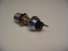
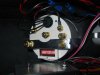
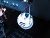
Speedometer calibration

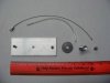
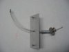
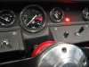
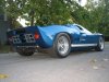
The weather in Southern Illinois was perfect today, with clear blue sky and high temps around 70. Ryan and I decided to take the GT out on the highway for the first time. We took along the GPS so we could calibrate the speedo. When traveling at a true speed of 60 MPH the speedometer indicated 110. The speedometer was easily removed, thanks to the knurled knobs used to install it so many months ago, and the DIP switches adjusted so the following were open: 3, 4, 10, 12. This resulted in an indicated speed within a couple of MPH of the true speed indicated on the GPS. The speedometer read nice and steady with no fluctuations or ‘spikes’ of the needle

The short message: Preset the DIP switches to make the following open: 3, 4, 10, 12. That should get you within two or 3 MPH using the 15 inch tires supplied by RCR.

99% DONE ! ! !
 

Attachments

  • SpeedometerB.JPG
    SpeedometerB.JPG
    126.1 KB · Views: 533
  • SpeedometerCalib.JPG
    SpeedometerCalib.JPG
    121.6 KB · Views: 546

Chuck

Supporter
100% DONE with the A list. Now on to the B list. But first, off to Run and Gun . . . . .
 

Attachments

  • Oct08D.jpg
    Oct08D.jpg
    53.9 KB · Views: 775
  • Oct08E.jpg
    Oct08E.jpg
    50.4 KB · Views: 770
  • Oct08C.jpg
    Oct08C.jpg
    63.2 KB · Views: 802
DITTO TO KEITH'S COMMENT! WELL DONE! Alas, wanting to attend R & G but
schedule does not permit. Really wanting to see a running SL-C.
 

Rob

Lifetime Supporter
EXCELLENT...!!!!! Looks great boys. Looks great.....

Can't wait to see the R&G pics.
 
Back
Top