Chuck and Ryan's RCR Build

Chuck

Supporter
Radiator, Part II

A vent line was added, connecting the cool / input side of the radiator to the connection on the top of the expansion tank. This permits any trapped air to vent from the radiator. Three eighths inch aluminum tubing was used to fabricate a long, straight line, equal in length to the long coolant tube extending through the center tunnel. This was run through the tunnel on top of the two coolant tubes. Two additional aluminum lines were fabricated to complete the connections at the front and the back.

Three eighths inch hose was used to complete the connections. Be sure to use heater hose, not fuel line hose. It is available at most car part stores. Fuel line hose does not hold up well to antifreeze.

The drain fitting on the top of the radiator on the side where the coolant enters the radiator was replaced with a right angle and straight fitting. Teflon tape was used so it could be positioned tightly where we wanted it.

I found very little information regarding this subject. Carroll Smith describes this technique in one of his books. Some suggest using a smaller line, perhaps a quarter inch. Based upon our initial experience running the engine, this set up seems to work appropriately and the three eighths inch tubing should, hopefully, not be an issue.
 

Attachments

  • RadiatorVent2.JPG
    RadiatorVent2.JPG
    145.6 KB · Views: 1,677

Chuck

Supporter
Tunnel Plumbing

Six lines run through the tunnel: two 1 ½ coolant lines, a 3/8” coolant bleed line, two AC lines and the fire suppression line. All the lines, except the fire suppression tube, were placed inside an insulating sleeve from Cool It Thermo, Inc. It had to be a thin sleeve since there is little extra space with which to work.


Before placing the lines the brake fittings adjacent to the tunnel were secured, since doing so after the pipes are in place would be a challenge.


Various holes were also drilled for the shifter and center console before the tubes were placed.

The copper line for the fire suppression system will be fed through the tunnel later. Since it is a small diameter copper line, it should slide easily through the tunnel.

Now that the tubes are in place there will be NO MORE DRILLLING on the tunnel.
 

Attachments

  • RadiatorTubeInsul.JPG
    RadiatorTubeInsul.JPG
    181 KB · Views: 1,684
Great progress Chuck. How are you running your electrical from the front to the engine bay?

Keep the pics coming!!

Bill D
 

Chuck

Supporter
Bill:

I will post a detailed description of the chassis wiring shortly, but to answer you question, we have two auxilary electrical panels, one in the aft compartment on the drivers side and one on the front passenger firewall area. A #8 wire runs from the alternator / battery connection to a junction point on the rear panel, and then another #8 wire runs from it to the front panel. That then becomes the power source for those items that are not fed through the dash and relay operated: fuel pumps. headlights, driving lights, MSD ignition, etc. Each of those items are separately fused. A number 8 wire is probably a bit of overkill, but better safe than sorry. This may sound a bit complex, but it actually is fairly straightforward and makes wiring the various items easier, since a power source is near by for either the front items or the rear items. More details to come.

Steve: The other advantage of a separate bracket for the fans is one can easily remove the fans as a unit without removing the radiator, shoud servicing ever be needed.

Chuck
 

Chuck

Supporter
First Engine Run

Saturday, January 19, 2008. Twelve degrees outside. The evening before the Prestone Extended Life coolant (the pink stuff) had been added; the last remaining project needed to start the engine. The GT had been pushed out of the garage and pulled back in with the exhaust facing out the garage door, so that it could be started inside the garage. This was it. Seven months of work assembling the chassis and we would now find out if we did it right.

Before turning the ignition switch on we pushed the start button, which turns over the engine without starting it. This got the oil flowing before firing it up.

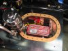
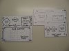
The ignition was turned on and we flipped the left fuel pump switch. The fuel gauges sprang to life, dutifully reporting the six gallons in the left and three in the right tank, which we had poured in a couple of weeks before. The fuel gauge showed exactly 12 volts coming from battery. Three pounds of pressure shown on the fuel pressure gauge after the large fuel filter / water separator had a chance to fill with fuel. A blast of cold air greeted us when we opened the garage door half way, just enough to clear the exhaust pipes.

Standing in front of the car where both the start button and the accelerator pedal could be reached, we pushed the button after a couple of primes on the pedal. It fired up instantly. After just a few minutes it was idling nicely around 1000 RPM. The oil pressure was showing about 50 pounds and the temperature gauge, after a seemingly long wait, started to move. All the gauges were working!

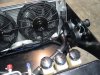
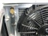
After a few minutes the fan thermostat activated the radiator cooling fans. But something about the temperature was not quite right. The engine thermostat was not opening. The coolant tube coming out of the top of the engine was cool, yet the engine seemed hot. Suddenly the engine temperature gauge started rising rapidly, to near the top of the scale.

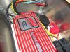
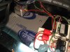
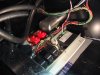
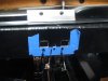
Obviously we had a problem, so time to shut down. I turned the ignition switch to off, but the engine kept running. Ryan grabbed a half inch wrench, removed the ground wire from the battery, and it still kept running. I reached into the compartment were the MSD ignition panel was mounted and started unplugging wires (later realizing it was the fuel pumps that I had unplugged). It still kept running. So finally, as a last resort, we just yanked the distributor wire off the coil, with a burst of static spark. It finally died. Good thing there was no video running.

Time for a break. Nothing like a sub sandwich from Quiznnos to help the analysis. We figured out both problems over lunch.

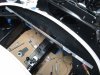
First, we reasoned that the engine did not have enough coolant despite the three gallons plus poured in the night before. We did not properly ‘burp’ it. Without coolant at the top of the engine, the thermostat would not open. The coolant vent line had not yet been installed, since we thought opening the vents on the top of the radiator as it was being filled would be sufficient for this initial test run. But now was as good a time as any to complete this little project. A couple of hours later and the vent line, noted in a previous post, was in place.

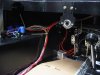
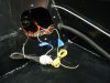
Next we removed the fan relay switch which is located just behind the thermostat in the fitting where a heater hose would normally be connected. Coolant was added until it reached the top. Then we jacked up the front of the car, to assure that this opening was indeed the high point on the engine and as we did so we heard some big air bubbles and saw the level of the coolant drop – clearly there had been air trapped in the back of the engine. Satisfied that as much coolant had been squeezed into the engine as possible, the fan relay switch was replaced and tightened.

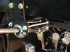
Second, we thought through why the engine would not die when turned off. The alternator, a Powermaster single wire GM unit, has a two prong connector as well as the single output terminal. The Painless wiring harness has detailed instruction describing the connection of the ‘exciter’ wire to the two prong terminals, so we followed the instructions and hooked them up. The alternator instructions, however, noted the following:

SPECIAL INSTRUCTIONS
1. One wire alternators require no jumpers from the internal regulator to the alternator battery post. A wire should run from the output terminal to the battery post, hence the term “one wire”.

We were aware of the foregoing admonition, but there was nothing to indicate connecting the two prong connector as recommended by Painless would prevent proper operation. So we elected to wire it, recognizing it may have to be revised. We reasoned that the MSD ignition was getting power from the alternator when the ignition was turned off, and that the ‘exciter’ wire was the culprit, since it was also connected to the ignition switch, thus providing an electrical source from the alternator when the ignition switch was turned off. We simply unplugged the two prong connector. A diode supplied with the MSD ignition could be inserted in the ‘exciter’ line, but why bother? This connection is not necessary with this alternator.

Time for the second run of the day. It was now about 9:00 pm. It was still miserably cold. But we could still see lights on at the neighbors house, so what the heck. Opened the garage door, turned on the ignition switch, pushed the start button, and it started right up. It settled into a nice idle, but then after just a few minutes it seemed to be starving for fuel. Pushing the accelerator pedal seemed to help briefly, but then it just died. “Dad, you forget to turn on the fuel pump.” Yea, that would do it. So a flick of the fuel pump switch and we restarted it. Good thing no video was running.

This time the water temperature gauge climbed appropriately. The auxiliary fans kicked in around 180 degrees on the gauge. The engine thermostat opened around 190 on the gauge, and then the temperature dropped in literally seconds to around 175. The coolant issue had been resolved!

Satisfied that we had made enough noise on a frigid Saturday night, we turned the ignition key to the ‘off’ position, and the car died instantly. That problem had also been solved. The neighbors could now go to bed.,

All in all, it was a rather satisfying day. All the gauges work exactly as they should. There do not appear to be any electrical gremlins anywhere and the engine starts and idles nicely. There are some engine and carb adjustment issues, but those will wait for another day, as we get back to finishing the chassis.

Sorry. No video. Yet.
 

Randy V

Moderator-Admin
Staff member
Admin
Lifetime Supporter
Congratulations guys!!!

As many cars and engines that I've built over the years, I've always thought of the first start to be parallel to a baby's cry to a doctor that just delivered it! :)
 

Rob

Lifetime Supporter
Congrats boys....!!
BTW, I agree with Randy's analogy (good one Randy). That initial start has always been a major adrenaline rush for me.
 

Chuck

Supporter
Chassis Wiring, Part I

Rear Power Board
In an earlier post, we noted that an opening in the left rear tank was cut out and covered with an oval plate. This chamber was used for wiring components. The MSD ignition module, fuel pump relays and a central wiring point were mounted on a section of white half inch Star Board (marine lumbar) measuring 9 ½” x 8” inches. This rear power board was then mounted on half inch nylon spacers with 3/16” button head stainless bolts.

Star Board is a wonderful product. It is used like wood, but is chemical resistant and requires no finishing. It provides an insulated surface for mounting electrical components. The white finish makes components, particularly in a dark location, easier to see. (It is also available in black). It should not, however, be used in temperatures over 200 degrees, so it cannot be used in close proximity to the engine or exhaust system. West Marine is a good source.

A Jegs Terminal Block, 555-10521 provided a central wiring point. It was fed with an 8 gauge wire from the alternator post, which was then connected to the starter and battery through a 50 amp fuse provided with the wiring kit per the Painless directions. The 50 amp fuse was located as close as possible to the battery – starter junction. The Jegs terminal block was the common point for connecting fuel pump relay power sources (which are also fused closed to the relays), the dashboard power source, and any other electrical needs not running through the dashboard. Another 8 gauge wire runs from this terminal block to the front power board. This keeps the wiring simple and accessible. It also keeps the high current accessories separate from the dash wiring. This is likely over kill, but adds a safety factor for little additional cost.

Bulkheads
The fuel pump wires and ignition coil wires were fed through a grommet on the inside wall of the bulkhead. The fuel pump wires were connected with removable connectors. The fuel level sending units have screws securing the wires which are accessible through the access plate. The coil wires are also secured with screw terminals. All the wiring behind the bulkhead can be disconnected through the access panel. Thus the bulkheads can be removed without having to cut any wires, should that ever be necessary.

Forward Power Board
A section of Star Board measuring 10 x 8 ¼ inches, with a notch for the lower control arm housing, was used for mounting the speedometer transducer, high beam, low beam and driving light relays. It was mounted on the floor a couple of inches behind the right front firewall to provide adequate clearance for the fittings mounted on the firewall. It is easily accessed from above and the white panel makes for a clean and easily seen mounting surface. It was fed with an 8 gauge wire connected to the Jegs Terminal Block mounted on the rear power board by the MSD ignition.

The power lines to the fan and the lights are separately fused. A Jegs terminal block provides a convenient junction point. Be sure to use a jumper between the two different size studs on the Jegs terminal block, since they are not internally connected.

The one inch aluminum angle on the rear edge provided a convenient mounting location for another grounding bolt (which is separately grounded with a wire to a chassis ground, since we don’t want to rely on the mounting screws for a proper ground in this location). Another aluminum angle was mounted on the front edge by the speedometer interface. If there are any issues with electrical interference a cover can be easily fabricated and placed over the speedometer interface using these aluminum angles as supports. Hopefully that won’t be an issue.

The speedometer interface connections were kept separate from the main wire harness to minimize the risk of interference.

A means of securing this panel so it could easily removed was sought in the event future servicing of any of the accessories or removal of the lower control arm bolt would be needed. Nutserts seemed the ideal solution since no real stress will be placed upon them in this application. Four were used. Now the screws can be easily removed from above. Enough slack wire was left in the harness so that this board could be lifted up and out of the way for easy servicing. Before the panel was installed for the final time a section of thermo acoustical insulation was placed beneath it, then four half inch nylon spacers raised the panel to clear the hardware on the bottom side.
 

Attachments

  • WiringMSDBoard2.JPG
    WiringMSDBoard2.JPG
    165.6 KB · Views: 1,698
  • RearPowerBoard1.JPG
    RearPowerBoard1.JPG
    212.8 KB · Views: 1,521
  • FrontPowerBoard3.JPG
    FrontPowerBoard3.JPG
    171 KB · Views: 1,527
  • FrontPowerBoard6.JPG
    FrontPowerBoard6.JPG
    160.6 KB · Views: 1,535
  • PowerBoardPattern.JPG
    PowerBoardPattern.JPG
    107.2 KB · Views: 1,503
Congratulations on the first time start!!! That will surely bring a smile to anyone's face for a long time.

I love your wiring. Wish I had done something similar.

Your craftsmanship is #1.

Cheers
Bill
 

Chuck

Supporter
Jac Mac

Good observation. Short answer: I don't know. But I have been thinking about ventilation options should heat be a problem The easiest: take the cover off. Vents could easily be added to that compartment as well. The more elaborate solution: add a small vent fan to that compartment (which I doubt would be needed).

I appreciate your comments and observations. Keep them coming!

Do you know what MSD stands for? My Spark Died... Don't ask me how I know....

Depends on how much exhaust pipe heat is in the general area. MSD boxes work pretty well in most engine compartments, so they are probably good to about 200 degrees. Also, DON'T LET THEM GET WET.. Again, don't ask me how I know about that one either....
 

Steve C

Steve
GT40s Supporter
Manny,

You are correct re temp and wet. I always insure a non wet location but to preclude condensation causing board components from shorting is good idea to spend a few more bucks and get the MSD box with a "HUMISEALED" PWB (like a glyptol coating)..

P/N is 6ALN..."N" denotes the coating.

Steve P2125
 

Chuck

Supporter
Dash Bracing

The nibbles and bites taken out of the chassis to clear the speedometer and vents as well as removing sections of the square tube supports on the underside had weakened the structure a bit. This was noticeable when one grabbed the steering wheel and pushed it up or down. Accordingly we fabricated a support, four feet long, from a section of aluminum angle, 1 ¼” x 1/16” thick. This was cut and trimmed to fit flush aft of the evaporator. Once secured with several ¼” bolts we noticed a significant improvement in the strength of the chassis. The up and down flex was greatly reduced.

The first picture shows the angle support bracket, cut to fit, resting on top of the chassis in the same position it was secured below the chassis. The second picture shows the right side of the bracket behind the speedometer opening.

The support bracket for the steering column had a bit of in and out flex. To eliminate the flex two lengths of 5/16 inch threaded rod, ten and a half inches long, were placed on either side of the steering support bracket to secure it to the chassis. This simple modification had a dramatic effect on the rigidity of the steering assembly. Don’t forget to tighten the tiny set screws on the steering column support, which are not easy to see.

To give us a bit of room for up – down and left – right adjustment of the steering column, the two holes for the bolts securing the bracket were enlarged, and made rectangular in shape. A backing plate was fabricated. This arrangement enabled adjustment of the column so that it is perfectly centered within the dash opening as well as permitting proper height adjustment. The top of the backing plate rests just below the bottom of the cross brace described above on the backside of the chassis. In the last picture the backing plate is setting on top of the chassis before it was installed.
 

Attachments

  • DashBrace3.JPG
    DashBrace3.JPG
    159.8 KB · Views: 1,400
  • DashBrace1.JPG
    DashBrace1.JPG
    93.9 KB · Views: 1,264
  • SteeringSupport3.JPG
    SteeringSupport3.JPG
    145.1 KB · Views: 1,436
  • SteeringBackingPlate.JPG
    SteeringBackingPlate.JPG
    127.9 KB · Views: 1,364
That looks like it is for the speedo. I thought there was plenty of clearance, now that my gauges are installed I need to go test fit mine.
 

Chuck

Supporter
The opening on the right is for the speedo. We cut as little as possible off the sides of the fiberglass dash board to clear the roll bar (see earlier post) which then requires a bit of a juggling act to slide the dash and roll bar into place together. This means that the dash needs to drop down and back as it slides into place, hence the larger opening. The AC air plenum also drive the dash "up" as it is slid into place, adding to the need for the larger opening. The fuse box and the three turn signal relays mounted on the bottom of the dash board (see earlier post) also made for a tight fit, so the hole was further enlarged.

It is like a puzzle. Depending on how the pieces are shaped, it goes together differently. If we had opted to take off more off the ends of the dash to clear the roll bar so that the dash would slide in after the roll bar was bolted in place, the opening would have been smaller. But keeping more of the dash required taking more of the aluminum so that the dash and roll bar could slide in together.

Once the opening for the speedo was cut we found we had taken a bite that essentially went to the to of the vertical metal. This would have been necessary regardless. The 'integrety' of this section was then compromised and flex was noted. Taking more did not really make much difference in the integreity of the structure, so we opted to take out what we needed and than added the brace as noted.

I am definitely not saying that our apporach is the 'right' way to do it. The nice thing about the RCR is that one can approach different issues differently to reach the desired result, depending upon ones priorities. My goal was to keep as much of the fiberglass dashboard intact as possible for asthetic reasons. There are clearly different ways to approch the project which may work as well or better.

As I reflect on it, perhaps removing the speedo, installing the dash, then installing the speedo after the dash is in place would enable one to make a smaller hole and slide it together. Our speedo wires have slack in them and knurled nuts were used to secure it, so this would have been an option, but I doubt it would have had much effect on the final result given the size of the opening needed to clear the speedo.

Last night we bolted down the AC unit for the final time (We hope) and set the dash and roll bar in place. The dash is good and solid. I will post some pics shortly.
 

Chuck

Supporter
Chassis Wiring, Part II

Wire Harness
The chassis wires coming from the dashboard had previously been separated into groups. Each group was separately labeled to indicate which side of the dash and whether it would go to the front or rear of the car. Within each group the wires had plugs attached to match the plugs already placed on the dash assembly. These separate groups of wire were placed in the car and loosely secured with wire ties. A collection of wires extends across the area behind the evaporator which was secured with a padded hose clamp. Additional clamps were added on the left and right sides of the chassis. The group of wires that goes to the back of the car was run along the left side of the driver’s seat, where there is a nice gap when the seat is installed. (Recall that the center spine is off center giving an extra couple of inches on the driver’s side). With the harness temporarily in place the separate wires could be pulled snug before securing them and placing a wrap over them.

Additional wires had to be added, which are not part of the dashboard harness and Painless kit.

(1) A blue wire was run from the compressor to the trinary switch.

(2) One 8 gauge red wire was run from the alternator / battery to the Jegs junction block located on the rear power board at the left rear. Another 8 gauge wire was run from the same junction block to the Jegs junction block on the front power board.

(3) A wire was connected to the engine block electrical thermostat switch and run forward to the cooling fan relay.

(4) Three wires were twisted tightly and wrapped with tape to connect the speedometer to the speedometer interface mounted on the forward power board. These wires were kept separate from the other wires by an inch or so to minimize interference. The three wires are for ground, B+, and sensor input. Remember that the power source comes directly from the accessory connection on the ignition switch and the ground connection is directly to the chassis, not to the dash ground bus used for instrument and switch ground connections. The speedometer connections must be directly wired and not share connections with the other switches and gauges.

The rear light wires were run along side the brake lines on either side of the engine, then routed straight back toward the respective lights. This results in an inconspicuous, neat layout.

The wires were wrapped with Painless Powerbraid Wire Wrap. This is a new product which provides a really clean, professional result. We prefer it to the convoluted tubing usually used. It comes in ¼”, ½”, ¾” and 1 ½” diameter. Although it stays in place well, an occasional wire tie is a good idea.

There will be a group of wires running vertically on the left side from the floor upward, forward of the dash which may be visible. Check out some old pictures and one will see a similar cluster of wires on many of the original GT’s. With the black wire wrap it will be inconspicuous. Whether we cover it with carpet or leave it exposed remains to be seen.

Four ground posts were placed, one on each side of the dash and on both sides of the engine compartment (by the rear power board on the left, and the battery on the right). We used quarter inch stainless button head screws. The holes were drilled and tapped so that the screws could be tightly screwed into the chassis to assure a good electrical connection. (With a bare aluminum chassis, tapping the hole would be less important). A star lock washer and standard stainless nut was used to secure the ground wire lugs to each bolt. Recall that we have at least two ground posts for the dash. One cannot have too many ground connections!

Our goal was an engine compartment as free of visible wiring as possible, yet all the wiring remains easily accessible.

The forward section wires were routed along the lower edge of the radiator. The wires for the head lights, driving lights, turn signals and marker lights were bundled on the left and right sides, to be connected later. Connections for the trinary switch and windshield washer were run behind the brake and clutch fluid reservoirs. All of these wire groups were wrapped with Painless Powerbraid Wire Wrap and secured with padded clamps. A ground terminal was placed on the lower center of the radiator fan bracket. Although it is grounded through the mechanical connections, a separate 8 gauge wire was connected to a dedicated ground stud to assure a solid ground connection.

In the third picture three coils of wire are visible. These are extra wires for the oil temp gauge (which we do not yet have), an auxiliary fan in the engine compartment, and a connection for the red dash warning light. These wires will be left in the aft compartment for future use. The stainless braided line is the throttle cable, which will be concealed beneath the carpeting.
 

Attachments

  • WireHarness3.JPG
    WireHarness3.JPG
    157.2 KB · Views: 1,146
  • wireharness7.JPG
    wireharness7.JPG
    125.8 KB · Views: 1,098
  • WireHarness4.JPG
    WireHarness4.JPG
    156.5 KB · Views: 1,076
  • WireHarness9.JPG
    WireHarness9.JPG
    199.1 KB · Views: 1,133
Back
Top