Chuck and Ryan's RCR Build

Chuck

Supporter
Air and Heat, The Plenum

We are doing posts a bit backwards. The AC system was something which we worked on a bit at a time for several months as various minor issues were sorted. The final instal was the day we drove the car.

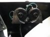
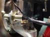
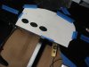
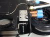
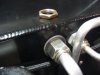
The evaporator was temporarily installed while the dash was being fitted to make sure there were no spacing issues. The unit was installed as far aft as possible, about a quarter inch from the rear lip on the dash. The three vents were exactly centered left to right. There are two threaded support rods on top of the AC unit. Once satisfied with the location, the support bolts were trimmed to about a quarter inch above the chassis to avoid clearance problems with the dashboard.

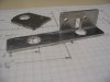
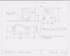
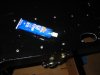
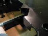
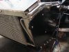
The plenum is a simple affair, but serves its intended function well. The only problem is that it was not designed for a car with a roll cage, so there is a clearance issue on both ends. A two inch section was cut out of each end and the end pieces were reattached with epoxy. They went together precisely. A single layer of fiberglass cloth was added to the seam we had created on the bottom side for a bit more support. The plenum was secured with screws which were pre drilled before the evaporator was installed. A thin piece of foam insulation, 3/8 x 5/16 along the bottom edge provided a seal, rather than silicon sealant, so that the plenum can be removed at a later date if necessary. (A ten foot roll was the exact amount needed, but buy two rolls, just in case). Note that it must be located as far aft as possible or it will not clear the dash vent on the top of the dashboard. A piece of acoustical / thermal insulation was placed on top of the metal dash panel where the bottom surface of the dash comes in contact with the bottom of fiberglass dash to minimize squeaks.

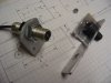
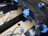
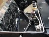
Installation of the evaporator requires removing, cutting, and reinstalling the one inch square tube supports. They are held in place with rivets. A bit of silicone sealer was dabbed on each rivet which will lie under the plenum after the tube supports were reinstalled. One can imagine the whistling sounds when the blower fan is turned on if those rivets were not sealed!

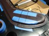
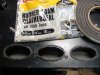
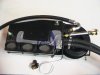
The three openings from the evaporator need to be sealed where they pass through the dash panel. Once could run a bead of caulk around them, but that would make subsequent removal of the evaporator more difficult. Instead we placed several straight pieces of foam insulation with adhesive backing, ½” wide x 9/16” thick on the underside of the chassis so that it would seal tightly against the evaporator when it was secured in place. We also squeezed 3/8 x 5/16 foam insulation, the same as was used to seal the plenum, around each opening, using a small screw driver to get it into place.

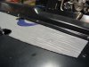
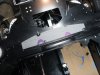
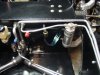
A section of acoustical / thermal insulation, 6” x 22”, was then placed on the underside of the chassis – dash, directly above the evaporator. Placing sections of this material on large flat areas of the chassis should help dampen possible vibration and noise.

More to come . . .
 

Attachments

  • ACPattern (2).JPG
    ACPattern (2).JPG
    108.4 KB · Views: 1,681
  • PlenumPreCut.JPG
    PlenumPreCut.JPG
    157 KB · Views: 1,704
  • PlenumLayout1.JPG
    PlenumLayout1.JPG
    176.8 KB · Views: 1,750
  • DashRivetsSealer.JPG
    DashRivetsSealer.JPG
    96.5 KB · Views: 1,613
  • ACDuctSeal2.JPG
    ACDuctSeal2.JPG
    160.4 KB · Views: 1,638
  • ACPlenum2.JPG
    ACPlenum2.JPG
    133.1 KB · Views: 1,640
Chuck, good tips on the a/c install. I trial fit everything, but will finish it this week. I'll also seal all the rivets with rtv. My plenum looks like the dog chewed it compared to yours! I already trimmed the ends and plan on laying up fiberglass to finish and seal it. Did you have to trim the front vertical edge of the dash support where the vents come through on either end like you did for the speedo?
 
Fran, are the RCR supplied plenums a recent addition to the kit ? In Deans build he appears to use pipes, normally used for plumbing, cut in half.
 
Ah, Fran to the rescue! The reason my plenum looks so different and won't lay flat on the cowl is that it actually bonds to the bottom of the dash in my right hand drive application. Once I flipped it upside down, it fit perfectly on the contours of the dash. Bonding will begin tomorrow...
 

Chuck

Supporter
Mark:

I did make substantial cuts in the vertical portion of the dash to clear the flexible tubing that connects the plenum ducts to the dash ducts on both sides. I also cut about a half inch off the plastic duct fittings so that the flexible duct would fit a bit better. In retrospect, I should have located the plenum ducts further forward about an inch or so, so that the flexible tubing would not be so cramped.

Hopefully this pic will help. With all the pics I have taken I can't believe I don't have something better to illustrate it.
 

Attachments

  • DashCutout.JPG
    DashCutout.JPG
    123.5 KB · Views: 1,587

Chuck

Supporter
Air and Heat, The Evaporator

Before installing the evaporator, we blew into one end while holding our finger on the other. Not the most sophisticated method for checking for leaks, but good thing we did. We heard the sound of air escaping inside the unit. I have never worked with an AC unit before and my knowledge base is somewhere around zero, but that did not seem right. I called Wayne at Hot Rod Air and he suggested having it pressure tested locally, which confirmed a leak. After returning it to Hot Rod Air, it was determined that the supplier of the coil assembly had missed a solder point. “That has never happened before.” Wayne promptly replaced the unit and returned it to us. The replacement passed the blow test. Wayne has been very responsive and provided us with excellent service on this and other issues.

The temperature sensing tube was installed. A small clip was used to secure it and a section of insulation cut from #12 wire was placed over the tube to protect against abrasion and vibration. A section of acoustical / thermal insulation was used to secure the tube to the top of the evaporator. That stuff sticks really well!

Water hoses were connected to the evaporator and run along the right side to a fitting on the front fire wall. The valve to control the heater temperature will be placed forward of the fire wall, so that in the event of a valve failure the hot water will not drain into the passenger area.

A substantial opening was cut on the brace under the dash to pass the large diameter AC hose. Although the hose would reach, it was a very tight fit. We contacted Wayne at Hot Rod Air and he provided us with replacement hoses. The large diameter hose totaled 44” and the small diameter hose totaled 40” from fitting end to fitting end. These dimensions worked out very well. The larger hose is routed on the driver side and neatly cleared the pedals and steering shaft without obstructing the access panel. The smaller hosed was routed on the passenger side, with the heater hoses. One bracket secures each AC line just inside the access opening on the front end.

Once the evaporator was in place we temporarily wired the blower to make sure air came out the side openings without any air leaks along the plenum. Once we knew there were no air leaks the dash was installed, hopefully the last time.

The simple push – pull lever to direct air either through the side vents or down towards the floor, described in a post long ago, worked very well.

The conclusion of the AC installation will be noted in our next post.
 

Attachments

  • ACThermalLine.JPG
    ACThermalLine.JPG
    167.3 KB · Views: 1,561
  • ACUnitReadyToInstall.JPG
    ACUnitReadyToInstall.JPG
    113.7 KB · Views: 1,576
  • ACPlenum4.JPG
    ACPlenum4.JPG
    147.9 KB · Views: 1,552

Chuck

Supporter
Air and Heat, Plumbing

The plumbing on the front end was completed without difficulty. The section of pipe which included the trinary switch is designed to be used on either a right or left hand drive car. That means on a right hand drive car it points down but on a left hand drive car it points up. We did not want it pointing up. A replacement was fabricated pointing downward. Minor point, but we wanted to keep the area above the plumbing clear.

The large fitting which passes through the front wall has a retaining nut. But the AC fitting could not be tightened down with this retaining nut installed due to the thickness of the chassis. This could be a trap, since one would assume it is tight when in fact it is not. One could perhaps ream out a bit of the chassis so the retaining nut could be tightened further or grind down the nut a bit. We simply removed the retaining nut and made a thick rubber washer to fill the space. Not as elegant as a nut, but this connection won’t be going anywhere and will not be stressed.

The smaller fitting tightened down without difficulty.

This is a really nicely designed system that looks good installed. Fran and his crew have clearly done a lot of research and development to put this heat and AC system together. Although Hot Rod Air supplies the hardware, the system is unique to the RCR cars. I am anxious to get it charged and operational.
 

Attachments

  • ACPlumbFitting.JPG
    ACPlumbFitting.JPG
    129.3 KB · Views: 1,287
  • ACPlumbing.JPG
    ACPlumbing.JPG
    167 KB · Views: 1,410
  • ACPlumbing5.JPG
    ACPlumbing5.JPG
    184.2 KB · Views: 1,343
  • ACPlumbing2.JPG
    ACPlumbing2.JPG
    141.8 KB · Views: 1,375
I must say that this is amazing. Not just the AC but your whole build. I jaw drops every time I check on this thread. Your front section looks like a factory design piece! I am going into the garage to take mine apart again. I have already had the whole car painted 3 times just trying to keep up with the RCR builders.
 

Chuck

Supporter
Dean:

You have the ultimate track - proven RCR GT40. You should revel in your success and, instead of messing with perfection, start another car. Like a 917 or a Mark IV perhaps?
 
Chuck,

I'm a new guy to posting on this site. I have sent you a PM. I have followed and I'm quite impressed, to the point of wanting to duplicate some (read "a lot") of Ryan's and your incredible build.

Between Ron McCall (thanks for letting me visit your place last summer), Dean L, Bill D, you and Ryan, and Fran's incredible company I have enough ideas to build six cars.
My RCR40 is on order! :pepper:

Later,
Howard
 

Rob

Lifetime Supporter
Congratulations Howard. Welcome to the RCR owners club... rockonsmilerockonsmile
 

Chuck

Supporter
Howard:

Welcome aboard! We have had a blast building this car and I am sure you will as well. Thanks for the kind comments. Be sure to keep us updated on your progress.

Chcu
 

Chuck

Supporter
Horns

Horns were ordered from Tri State Motorsports. They are compact and put out a good, loud note.

http://www.tristatemotorsports.com/DetailsSelect.cfm?ID=4090#

A Lucas push button activates the horn. We wanted the horn button and turn signal switches to be a finger’s reach from the steering wheel rim where one can reach them instinctively without having to search. Accordingly the horn button is the first switch to the right of the steering column and the turn signal is the second.

The Painless wiring harness includes a relay on the fuse block for the horn, so no additional relay was needed.

Check Horn Test at this link:

http://www.youtube.com/user/ChucksCars
 

Attachments

  • horns1.JPG
    horns1.JPG
    116.2 KB · Views: 941
  • HornButton.JPG
    HornButton.JPG
    146.3 KB · Views: 955

Chuck

Supporter
Speedometer Sensor

The sensor supplied with the RCR Classic Instruments is part number SN78. The directions recommend 6000 to 11000 pulses per mile. When mounted on the front hub with a 24 inch tire, with eight bolts on the rotor to trigger the magnetic signal, the math works out to about 6700 pulses per mile, which is within the acceptable range.

A bracket was fabricated to secure the sensor to the right front hub. An eighth inch thick by one inch section of aluminum angle and a one and a half inch section of flat aluminum stock were used. The holes in the hub accommodate a half inch bolt. A socket head cap screw was used, and still the clearance was tight, requiring that an opening be beveled in the bracket to clear the bolt head. By moving the flat portion of the bracket supporting the sensor up and down slightly the sensor can be perfectly centered over the bolts on the brake rotor.

Although a diagram is attached, one should make a pattern for their specific application. It took several hours of careful filing to get an exact fit and bevel the opening for the head of the bolt to clear. When finally bolted in place, the assembly was stout and the sensor was perfectly centered over the bolts.

The signal from the sensor to the transducer is weak. Steps were taken to prevent stray interference. The connection from the speedometer interface to the sensor was made with shielded instrument cable from West Marine, part number 198754. This wire has a red, black, and ground conductor with a metallic shield. The shield wire was grounded on both ends. This resulted in both a good mechanical connection and good electrical connection.

Does it work? Spinning the wheel with the car up on jacks we reached 20 MPH, so we are optimistic. It will be a while before the car is driven fast enough to properly calibrate it.
 

Attachments

  • SpeedoBracket1.JPG
    SpeedoBracket1.JPG
    103.5 KB · Views: 773
  • SpeedoBracket2.JPG
    SpeedoBracket2.JPG
    143.4 KB · Views: 802
  • SpeedoBracket3.JPG
    SpeedoBracket3.JPG
    147 KB · Views: 926
  • DiagramSpeedoBracket 001.jpg
    DiagramSpeedoBracket 001.jpg
    15.7 KB · Views: 814
Back
Top