Classic HorsePower Scratch GT40

Devin

Supporter
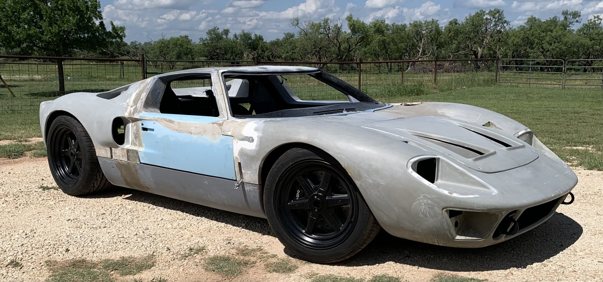
Been a while since I’ve had all the bodywork all back together but since all the guide pins, latches and hinges are in place, it was time. Now I’m working on front clam dzus fasteners before final bodywork leveling and front end gaps. Also time to start looking at fabrication of the deeper twin nostrils (currently not so deep) that will move the air in the right direction post radiator & fans.
IMG_1724.jpeg
 
Last edited:

Devin

Supporter
In preparation for the twin nostril modifications, it was time to secure the panel with Dzus fasteners. After a lot of measuring, marking, drilling, measuring, modifications, measuring, drilling and installing, the fasteners are complete. Through the process I realized that one corner of the panel opening wasn’t deep enough to allow proper securing of the wire retainer and proper flush fitting of the dzus once in place. A quick cut (albeit not fully cut free) of the corner support structure allowed it to be displaced another 2mm deeper and epoxied back into its new location. A little bodywork and no one will notice the correction to that corner structure.

The twin 9” Spal fans arrived and I designed and ordered the fan shroud on SendCutSend.com to be delivered in about 10 days. This will be my first experience with them and will enter a build log entry specifically on my impressions using their website and end product.

IMG_1729.jpeg

IMG_1734.jpeg
 

Devin

Supporter
I felt the need to drop the drivetrain back into the chassis today. I’m getting ready to source and design the remote oil filter and cooling system so needed things in place to see the best location for components and lines. Also was an opportunity to clearance the bulkhead panel and the rear clamshell interference with the transaxle. Lots more planning and engineering yet to come on the fire suppression, cooling, electrical and exhaust system before thinking of removing the drivetrain for the last time.
IMG_1746.jpeg

IMG_1749.jpeg

IMG_1756.jpeg

IMG_1757.jpeg

IMG_1755.jpeg
 
I felt the need to drop the drivetrain back into the chassis today. I’m getting ready to source and design the remote oil filter and cooling system so needed things in place to see the best location for components and lines. Also was an opportunity to clearance the bulkhead panel and the rear clamshell interference with the transaxle. Lots more planning and engineering yet to come on the fire suppression, cooling, electrical and exhaust system before thinking of removing the drivetrain for the last time.
View attachment 154113
View attachment 154114
View attachment 154115
View attachment 154116
View attachment 154117

I felt the need to drop the drivetrain back into the chassis today. I’m getting ready to source and design the remote oil filter and cooling system so needed things in place to see the best location for components and lines. Also was an opportunity to clearance the bulkhead panel and the rear clamshell interference with the transaxle. Lots more planning and engineering yet to come on the fire suppression, cooling, electrical and exhaust system before thinking of removing the drivetrain for the last time.
View attachment 154113
View attachment 154114
View attachment 154115
View attachment 154116
View attachment 154117

I felt the need to drop the drivetrain back into the chassis today. I’m getting ready to source and design the remote oil filter and cooling system so needed things in place to see the best location for components and lines. Also was an opportunity to clearance the bulkhead panel and the rear clamshell interference with the transaxle. Lots more planning and engineering yet to come on the fire suppression, cooling, electrical and exhaust system before thinking of removing the drivetrain for the last time.
View attachment 154113
View attachment 154114
View attachment 154115
View attachment 154116
View attachment 154117
 

Attachments

  • IMG_20181219_172853664_HDR.jpg
    IMG_20181219_172853664_HDR.jpg
    388.8 KB · Views: 67

Devin

Supporter
Now that the engine is back in, I’ve been working the accessories, brackets, with their positioning and belt adjusters. I found that how I initially planned to position the AC compressor with its supplied turnbuckle adjust wasn’t going to allow spacing from the rear removable bulkhead panel. Spent a session of experimental positioning and varying lengths of adjustment point…ended up having to fabricate a custom length turnbuckle after ordering a set of paired rod ends. After some measurements and TIG welding, looks like it will work great and will order some correct sized bolts and spacers to complete.
IMG_1761.jpeg

IMG_1762.jpeg
 

Devin

Supporter
Where did you get your pully sets?
CVF Racing…www.cvfracing.com

I ended up ordering their alternator & AC (high mount) system. If you can’t tell, I flipped the AC extended mount upside down and lowered it one bolt hole. It still feels very solid and with the AC compressor rotated 90 degrees on its side will be just enough room for clearances and hose connections. I don’t care for their 3/8 bolts going through the 11mm compressor mount tabs so am currently sourcing an appropriate sized tubing/shim to take the slop out of the sizing mismatch and potential for belt misalignment. Once complete, I’ll source the appropriate length of drive belts.
 

Devin

Supporter
I ended up custom making and fitting shims inside the AC compressor mounting bracket to utilize the CVF mounting bolts, although I did have to order a couple of appropriate length & strength socket head cap screws to mount the adjuster turnbuckle. The shims were the key to make a super solid and precise fit for proper pulley alignment. I don’t know if I mentioned previously that I purchased a hydraulic AC line fitting crimper…it works like a champ and was the only way in my opinion to getting the best fitting lines correctly fabricated the first time and without issue of someone else trying to interpret my personal markings and angles required. In the end, I wish I had the courage and know how to buy one of these years ago.

After measuring the V-belt length and temporarily installing the new AC lines, I checked the bulkhead panel which needed additional clearancing with the addition of the drive belt.

IMG_1776.jpeg

IMG_1778.jpeg

IMG_1780.jpeg

IMG_1783.jpeg
 

Devin

Supporter
Worked on the lower coolant pipe to water pump return. Found I needed a 45 degree elbow on each end (center pipe & pump inlet) of a 90 degree aluminum elbow. Of course nothing just ever seems to bolt together and needs modified so I found another reason to use my handy bead crimping tool. It worked so much easier on this aluminum than the stainless center pipes. Since this pipe is virtually the lowest coolant on the car, I also wanted a drain petcock for any servicing of the system. After locating the best position, I TIG welded a 1/4 NPT bung in the elbow and was able to contour/level the inside of the pipe to reduce any coolant flow restrictions.

My first time (other than some practice scraps and building my small console frame) welding an aluminum & water tight project, so am pleased with the results and appears to be sealed without any issues. Small victories keep my enthusiasm and spirits up for more work in the Texas summer heat!
IMG_1784.jpeg

IMG_1787.jpeg

IMG_1788.jpeg
 

Devin

Supporter
DO you have any other pictures or a diagram on how you are running your coolant hoses from the motor to the center pipes?
Joe,

Currently waiting on my CVF Racing thermostat housing (90 degree swivel) to arrive to “finalize” my right side hose & tube routing. My plan is a similar 45/90/90 that will go between the alternator and water pump to the thermostat. Stay by for completion and pics in about 10 days. In the meantime I’ll be working another 1/2 NPT bung on the same return pipe that will be connecting it to the expansion tank and 5/8” lines for the heater (I know…really not necessary in Texas but I have a dream of driving it somewhere cooler one day ).

Devin
 

Devin

Supporter
More fittings and hoses delivered and just a couple more to call it complete (for now). All the thought, planning, fabricating and engineering are finally coming to fruition. I knew things were going to be compact and tight but as we know it’s the nature of the design and making the best of it. Attached pic is the “heart of the beast”.

658D377B-2086-4D4D-8F9E-45B192AF4D04.jpeg
 
Back
Top