Clive's Scratchbuild

Paul,

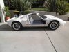
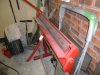
Looking at the brightest red I can source at this stage. Dictated by 'safety' considerations. Many of our population, of south east asian decent, appear to have very poor eyesight when driving, confirmed a number of times when out in the Clubman.

Decided I need all the help I can get to avoid comings-together. Probably just run side stripes, rather than over the top.

Clive
 
A breakthrough.

I have long been concerned at mating the 302 to the inverted Renault UN1. The flywheel being the main problem, fitting into the Renault bellhousing.

Returning to an old school engine rebuilder, I am now going with a Falcon 6 cylinder flywheel (same bolt pattern as the 302 crank), machined down to receive a Subaru ring gear (about 315mm diameter), and the 302 bottom end rebalanced as a unit. So simple when age and experience enter the equation :)

Clive
 
After 15 years of sitting on the build frame, the 40 has finally hit the deck.:happy::happy::happy:

Will now be ready to trailer it to the Wheels show in a couple of weeks time.

Had a rethink about the front suspension, and decided I was a little concerned at butt welds to the top arms, as these would take all the suspension loads. A redesign and remake result in a considerably stronger setup. I probably didn't need to worry, as on cutting the old arms apart, I found they could probably have supported a truck.

A couple of piccies.

Clive
 

Attachments

  • P3060029.JPG
    P3060029.JPG
    129.7 KB · Views: 641
  • P3070031.JPG
    P3070031.JPG
    134.1 KB · Views: 650
  • P3070032.JPG
    P3070032.JPG
    101.8 KB · Views: 697
  • P3070033.JPG
    P3070033.JPG
    103.2 KB · Views: 634
What a diference a couple of days make. :pleased::pleased:

Looking good for the Wheels car show in two weeks.

Clve
 

Attachments

  • P3130038.JPG
    P3130038.JPG
    104.6 KB · Views: 642
  • P3130040.JPG
    P3130040.JPG
    108.1 KB · Views: 571
  • P3130041.JPG
    P3130041.JPG
    107.3 KB · Views: 605
  • P3130042.JPG
    P3130042.JPG
    100.1 KB · Views: 607
  • P3130046.JPG
    P3130046.JPG
    108.1 KB · Views: 686
The engine is also falling into place. Having it rebuilt in 302 guise, but have acquired alloy Procomp heads, roller rockers, 4 barrel throttle body, & EFI manifold at a very economical price from ebay. Will need to plumb the EFI fuel rails, but I would be anticipating about 400FWHP for about $2.5K. Computer on top of this.

Pleasing!

Clive
 
We have a five day holiday over Easter here in Aust, so looking to make the most of it.

After the 'Wheels' show a couple of weeks ago, it was a case of strip down to bare chassis, and add the couple of brackets still needing to be welded. Then drove the neighbors mad with grinding/filing welds so the chassis looks as neat as I can get it.

Got the chassis back yesterday from the grit blaster/powdercoater. Looks a treat. Looking at making some real inroads over the next couple of days, concentrating on the miriad internal panels. Going over each one, checking for square, no burrs, straight edges, all prior to painting the inside with the 'Lizard Skin' type product, and the exterior with two pack satin black.

The rivetts have been painted satin black and the bonding goop is ready. Will see where we end up in a couple of days.

Clive
 

Attachments

  • P4220010.JPG
    P4220010.JPG
    100.1 KB · Views: 599
  • P4220011.JPG
    P4220011.JPG
    98.2 KB · Views: 550
  • P4220012.JPG
    P4220012.JPG
    123.2 KB · Views: 566

Randy V

Moderator-Admin
Staff member
Admin
Lifetime Supporter
A lot of nice effort done there Clive.. Drilling all those rivets out must have been a treat eh? I hope you've a pneumatic rivet gun - should make the reassembly go much nicer. Hopefully the powder coating has not added so much that the rivets no longer fit..
 

Terry Oxandale

Skinny Man
Nice build Cleve. I was looking at all your photos and never could figure out the front suspension design. How does the lower shock mount operate to allow the suspension to move? Fascinating design, but I can't see wherer the pull-rod compresses the shock/spring. Does the upper portion of this lower bracket pivot (and I just can't see the link in the photos)?
 
Terry,
As I see it, when the upper A arm goes up it lifts the rod which is on a fulcrum to the shock. Bit of neat geometry. First time I have seen anything like this. Clive what are the ratios of the unit and what rating is the shock. I would thinik it would have to be pretty high and have a very short travel. Lot of inspiration there.

Bill
 
Thanks for the comments, guys.

The panels were only held on with 3 or 4 rivetts each for the show, as I knew it would be coming apart :laugh:.

The rocker is pivoted in behind the lower shock area. The ratio was dictated by how close I could get the shock lower ball joint to the rod end, without them binding on full droop. The ratio has worked out at about 2:3 - about 80mm of shock travel gives 120mm of wheel travel. I have installed fairly heavy springs, and will fine tune down the track.

Today was spent filing, linishing and giving all the panels an acid bath as a pre-etch. Turns out there's over 40 individual panels, with a couple still to come. Tomorrow=Paint :happy::happy:

Clive
 
Clive, have you bend all these panels with that red folder in pic #1 from post #27 ? If so can you please put up a pic or two of the folder and the method how to get the radius in the bend ?

Thank you, Z.C.
 
ZC,

Piccies attached.

This unit was given to me, and it works suprisingly well. Basis is a guillotine blade, mounted on angle iron, with a second angle iron as the anvil/bending arm.

Did most of the bends needed, but the sill panels are a lot larger, which required a set of rollers and a long bender.

Clive
 

Attachments

  • P4240014.JPG
    P4240014.JPG
    103 KB · Views: 496
  • P4240015.JPG
    P4240015.JPG
    107.4 KB · Views: 463
  • P4240016.JPG
    P4240016.JPG
    98.8 KB · Views: 441
While I'm playing with the internal panelling, and the chassis is sitting there all bright and shiny, I've decided to throw a tape over it.

Stage one is the floor level. I have it as a .DXF file for those who can use it - my preffered file type, as the dimensions are locked in. However, I only seem to be able to post here as a .bmp file. Overall dimensions are 2940 x 1140mm.

Tube sizes are 40x40 and 25x25mm, as can be seen from the file. Only funny at this level is the tube under the motor/gearbox area, which is 25mm wide but 50mm high.

I will continue to the next level up, and would appreciate comment.

Clive
 

Attachments

  • GTFRAME1.BMP
    101.8 KB · Views: 360
It took a couple of days longer to paint the panels, but very pleased with the result. The level of satin gloss matches the powdercoated chassis perfectly. All panels have the ceramic bead treatment to the inner side, but apart from a little extra sanding, the finish is identical.

Clive
 

Attachments

  • P5010026.JPG
    P5010026.JPG
    104.9 KB · Views: 515
  • P5010027.JPG
    P5010027.JPG
    106.7 KB · Views: 480
  • P5010029.JPG
    P5010029.JPG
    102.9 KB · Views: 521

Randy V

Moderator-Admin
Staff member
Admin
Lifetime Supporter
Coming together quite nicely.. You're right the matchup is perfect!
 
Not happy.

Been fixing the internal panels and going well. Decided I had better make sure I could thread the seatbelts through the appropriate path. The driver's side was a battle, but I got there.

However, for some reason I have yet to sort out, the passenger side was never going to fit. I have had to cut the bottom mount where the inertia unit lives out of the frame, and will have to relocate it about 15mm back. This mount was very well welded into the frame, and was a major pain to cut out for relocation.

During this exercise, I have discovered that my 100mph adhesive is absolutely useless when in contact with powdercoat. I would appreciate any suggestions for suitable bonding material to powdercoat.

Clive
 

Randy V

Moderator-Admin
Staff member
Admin
Lifetime Supporter
Sorry to hear of the poor fit... :(

Powder coating is really just plastic and it is very smooth (non porous) when properly cured. You need to roughen up the surface or otherwise etch it in order to make a good adhesion to it..

JB Weld Epoxy is known to be some of the toughest stuff in the world that will adhere to darned near anything if the surfaces are properly prepared. Not sure of what it is that you want to bond.
 
Back
Top