Columbus Ohio RCR40

Sorry everyone, looks like GT40s.com doesn't want me to have vertically oriented photos tonight... I fiddled with it for about 5 minutes and couldn't fix things so not sure why I am just now having this trouble.

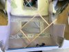
The drivers door leading edge was very far from matching up with the A-pillar near the windshield. Luckily this also easily could be bent in with some gentle clamping force and plenty of heat.

IMG_1321.jpg


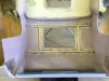
Once the doors were fitting how I liked and panel gaps at about 85% I moved onto the door latches as I wanted to have these installed and working before I finalize any body gaps. I opted to mount the plate on the outside of the door. This way the plate sandwiches the fiberglass between itself and the actual bear claw latch. I think this setup is stronger/more solid. Plus the plate will look great powder coated black. Please excuse the rough initial cuts in the fiberglass here, I will certainly circle back to clean everything up once I nail down the functionality.

I plan to circle back at a later time and install some metal beams across the door for some anti-intrusion. Still thinking through how to bring it all together.

IMG_1326.jpg


Currently I am REALLY struggling with mounting the actual exterior door latch. I hate the idea of simply pinning it through holes in the fiberglass, and lets be honest there needs to be some adjustment in the pinning location to get it perfectly lined up and flush with the door. I also ran out of fiberglass for the latch pin. Currently thinking about fiber-glassing in some aluminum angle stock and building some adjustment into that.

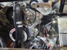
Also the latch lever is inconveniently located at the bottom of the latch far from the lever. Currently I mocked up some scrap aluminum to bolt in there to test things but eventually I think I will weld some steel onto this latch so the arm extends vertically upward closer to the handle arm. This will be much more advantageous for the lever system and also I don't need to worry about a bolt loosening up and preventing my door from opening.

IMG_1325.jpg


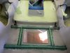
To mount the door jamb bolts I trimmed down the supplied part so it wasn't as long, and simply welded in some new steel to provide the necessary offset. This was a bit tricky to get to line up well on the first try. I also ran into a bit of an issue where the bolts holding the latch plate to the door stuck out far enough to catch the door jamb mount slightly. Currently I just have some extra washers to stick the bolt out further which then allowed me to have a little less offset for the mount. Pretty happy with how this turned out, definitely going to circle back and reinforce the mount.

IMG_1330.jpg


IMG_1328.jpg


IMG_1332.jpg


Hopefully soon I will have better mounting for the exterior latches and can do the same thing for the drivers door. From there it is just lots of sanding. Not super happy with how the passenger door lines up with the spider from the supplier... as you can see from the above picture a lot of work will be needed to even things out. The last two major milestones for the body will be switching the front nose to a hinge style mount so it can be tilted forward and adding the +2 flares... should be a fun time!!!

happy new year all!!
 
January was a very productive month.
Both doors mount, have hard mounted door handles, and door jambs. Pretty happy with how everything turned out. Mounting the door handles in a manner where the pin position is adjustable turned out to work great. The door handles are able to be precisely adjusted to fit just right. I have one picture of an early mock up. Essentially just two pieces of aluminum angle iron each with a floating plate with a hole in it just the right size for the handle pin. The angle iron got glassed in to the door.

IMG_1361.jpg


I noticed there are not a lot of posts about installing +2 flares on the rear clip. I decided I'd post a handful of pictures of the way we decided to go about it in case it helps others. I am sure there are many ways to do this, each with their own drawbacks and benefits. We followed some tips we got while picking up the kit at RCR and are very very happy with the results. The panels were bonded with 610 from West Systems. Lots of self tapping screws worked great to hold the panels together and in place. I tried to cut the old fender out in a way that was conducive to minimal body work to smooth out the seam. So far things look pretty good.

IMG_1402.jpg


it was hilarious to see the car without a rear fender. Pretty nerve racking too. No going back now!!

IMG_1404.jpg


Some trimming of the +2 panel and it started to fit pretty well for the first time. This was the first glimpse of our car with the flares.

IMG_1411.jpg


IMG_1407.jpg


IMG_1423.jpg


IMG_1437.jpg


The other side went a lot quicker.

IMG_1495.jpg


Next up were the rocker flare panels. This surprisingly difficult to get "good enough". The flare panels were quite rough, and had to be heated a lot to get a reasonable fit.

IMG_1498.jpg


A trick that worked well for us was to use part of the old rocker that needed to be cut out to serve as a backing for the new panel.
I will go back and smooth it and re-enforce things.
 
IMG_1499.jpg


This was as close as I could get the passenger side. I am happy with the seam but the wheel lip flare just wouldn't line up just right.
It will need a lot of additional work.

IMG_1504.jpg


The drivers side went much smoother/better.

IMG_1506.jpg


IMG_1507.jpg


Next up is some light body work. The curves of the rear clip are so organic it will take a lot of careful sanding and time.
 
Small update this time... Just lots and lots of sanding. This is our first fiberglass body, but I believe we are through most of the learning curve.
The rear clip is finally starting to come together, I am really happy with it.

IMG_1624.jpg


Body alignment pins also went in for the rear clip. We tried to get away with one for both sides, but I wasn't happy with the rigidity. One on each side of the slot for the Hartwell latches really locked things up nicely on each side!

IMG_1610.jpg


I am guess we probably have another month or so of body work and I think it will finally be time to switch gears. Probably mounting the motor!
 

Randy V

Moderator-Admin
Staff member
Admin
Lifetime Supporter
Looking good Nick!
I had a heckuva time getting my wide hips and clip where I wanted them to be. Especially getting the rear deck “flat” between the arches. I built a rear support structure from 1x1 oak from the big box store and glassed it in place. 200% better results!!!
 

Attachments

  • E4712ECD-996B-4EC0-97C4-6AC2DE8EA62A.jpeg
    E4712ECD-996B-4EC0-97C4-6AC2DE8EA62A.jpeg
    329.9 KB · Views: 192
  • 2809811C-A2E0-4ACA-B5FC-6AE69C9F8CA6.jpeg
    2809811C-A2E0-4ACA-B5FC-6AE69C9F8CA6.jpeg
    319.5 KB · Views: 196
  • 48B934C6-E29B-4C0A-A6B2-DE2E3C0C75DC.jpeg
    48B934C6-E29B-4C0A-A6B2-DE2E3C0C75DC.jpeg
    308.9 KB · Views: 196
Hey Nick,
Great job on the build so far. Although I am a new member, I am far from new to the forum. I have been watching peoples builds for several years now trying to learn everything I can before I embark on my own.
In saying that, I live in Danville OH and I would love to come take a look at your car! When I decide to pull the trigger I too plan on buying a kit from RCR. They are close and I like the aluminum monocoque design.

Let me know if you wouldn‘t mind having a random guest stop by and pick your brain.

keep up the good work, I can’t wait to see it completed!
 

Brian Kissel

Staff member
Admin
Lifetime Supporter
Welcome to GT40S Nate. You are doing the right thing by reading all the builds and asking questions. Good luck with your future build.
Sorry for the thread drift Nick.
Carry on !!!
Regards Brian
 
Hey Nick,
Great job on the build so far. Although I am a new member, I am far from new to the forum. I have been watching peoples builds for several years now trying to learn everything I can before I embark on my own.
In saying that, I live in Danville OH and I would love to come take a look at your car! When I decide to pull the trigger I too plan on buying a kit from RCR. They are close and I like the aluminum monocoque design.

Let me know if you wouldn‘t mind having a random guest stop by and pick your brain.

keep up the good work, I can’t wait to see it completed!

Hey Nate, welcome to the Forum! PM sent.
 
The past month was full of sanding and more sanding. However eventually things shifted to getting the front clip mounted finally!

I took heavy inspiration from @Mstarkey3 for mounting the front clip in a way that lets it rotate forward.

IMG_1840.JPG

IMG_1843.JPG


I landed on two 5/8" bolts that thread into coupling nuts that I cut down slightly and welded to a steel plate. I liked the idea of some extra threads. Then as if the 5/8" bolt wasn't overkill enough I welded in two gussets. I guess that just shows the faith I have in my welds... lol.
This was the best solution we could think of as the radiator is directly on the far side of the frame here so the bolt cannot pass through.

IMG_1836.JPG


IMG_1838.JPG


These bolts pass through the clip and a 1/8" aluminum plate bent to follow the body as it has a curve here.

IMG_1844.JPG


IMG_1842.JPG


I plan to circle back to this for a few further improvements:
1. I want to keep the bolts from backing out with either a jam nut or capturing the head of the bolt. My original plan is to capture the bolt head on the inside of the clip with a cap that then itself bolts to the front clip eliminating any bolt rotation independent of the body. This way the body can open by rotating on the threads and the bolt could never back out. Also this solution allows the nose of the clip to easily be adjusted to left and right by tightening/loosening the large bolts on both sides. If this doesn't work out a jam nut would secure the bolt, but then the body would rotate on the bolt threads. Not the end of the world imo.
2. The bolt heads are not perpendicular to the aluminum plates due to the shape of the body. While maybe not required I think it would be nice to build up some weld around the hole in this area and then carefully grind it flat to the bolt for a nice surface to mate too.
3. The plate borrows two bolts from that frame along the bottom that now need to be longer

Also we finished getting the center panel fit and clipped in. I decided to go with quick latches as I think they look cool, and are easily adapted to many different applications/heights. Getting the mounting buckets was a must here do to the close clearances. Also maybe this goes without saying, but don't cheap out on these if you decide to use these. You can buy 4 on amazon for a few dollars but they are garbage. I returned a set and ordered others from push button latches.com that were more expensive but a night and day difference in quality. These are the 1.25" mini "pro series".
The front two buckets just barely didn't fit on the original body flanges where I mounted them, I forgot to take a picture. I will go back and rebuild them slightly larger. You can make them fit, but I think the corresponding buttons on the outside of the panel would look wonky that close to the corner edge. The buckets are small enough that the clip can still rotate past the radiator with a comfortable amount of clearance.

Bonus points if you spotted the chief engineer sleeping on the job! Despicable! I thought she was a working breed!

Up next is final body gap fitment, swapping over the wiper mount, and Hartwell latches!

IMG_1853.JPG


IMG_1856.JPG


IMG_1852.JPG


IMG_1847.JPG
 
Wow time flies! Haven’t posted since May…

Summer is a busy time with family and friends, but the body work still got mostly completed. I’d say it’s at about 90% now. My plan is to leave the body as it is now and move on to everything else. Then down the line finish up the small stuff before paint. I don’t have any pictures really as it’s just boring body work and panel gap adjustments. Here’s one with lots of guide coat on the car to help get things even.

IMG_2248.jpeg


The engine and transmission went in the car for the first time a couple weeks ago. I’m happy with how it fits, and have picked out an engine mount bushing kit that’s on its way. It’s a self weld kit so I can get it to fit this very unique application lol.

mating the transaxle for the first time went ok. I was disappointed to see the RCR billet adapter interfered with bolts on the rear engine cover. It wasn’t a huge deal, I decided to just gently grind away some material where the bolt heads protruded. It fits great now.

IMG_2268.jpeg

Here you can see the gap due to interference

IMG_2270.jpeg

The offending bolts

IMG_2269.jpeg

The old grease trick comes in handy once again.

IMG_2274.jpeg

Finally in the car resting on some wood blocks until the mounts are welded in.

Also I was happy to see the starter fits the engine well. I just needed to grind one protrusion off the block for clearance. No need to modify the car frame.

once these engine mounts get welded in it’s time to order tons of parts and do some fun stuff.

1. fuel system / fuel tank mounting (took notes from @Mstarkey3 install, planning something similar)
2. Dry sump install
3. Intake parts test fit. There is very little clearance to the clamshell, I am going to have to get creative here lol.
4. Start exhaust mockup. Going to try and 3D print my own ICEengineworks
 
Engine mounts went great. I am super happy with how they turned out. Put a light coat of black spray paint to protect them from rusting, will probably powder coat them later.

I found a perfect "self-weld" kit online that included the perfect size bushings and bushing tube. It came with extra material to build your own arms but instead I modified the arms to accept the bushing tube. Worked like a dream.

IMG_2371[1].JPG


IMG_2374[1].JPG


IMG_2375[1].JPG


For sitting at a desk the majority of the time at work... I was happy with my MIG welds. I am excited to learn TIG on this car... just waiting for a good application to use it.

IMG_2377[1].JPG


I assembled them and tacked them lightly in place for a perfect fit.

Once the engine was in it was time to start planning intake/fuel/oiling.
My engine is fuel injected and the traditional intakes just won't work that have a large front opening to accept a throttle body. It can't face forward as the firewall is obviously there, and a traditional bundle of snakes prevents mounting the intake in reverse.
After lots of searching and planning I decided to try out a traditional single plane intake with a 4150 flange at the top.
Then I ordered one of Holley's throttle bodies for this kind of intake. It was a TPS and IAC valve integrated into it which I liked.
I would rather have a single throttle plate like what LS engines came with for simplicities sake... but packaging concerns won over that.
IMG_2382[1].JPG


IMG_2409[1].JPG


IMG_2412[1].JPG


I was expecting about 0.5" clearance to the rear window with this setup... I was shocked to have 1.5" instead. After checking parts the intake was significantly shorter than advertised. Pretty annoying as I put a good bit of time planning out these parts to maximize air cleaner size, when in reality I had a lot more room than I thought. I will probably upgrade to a large/nicer air cleaner seeing all the additional clearance I have now.

I had to completely change gears on my oiling system. I really wanted an Aviaid dry sump kit, but after doing some mock-ups with online templates I just couldn't make the pump fit without the frame needing to be significantly dished/cut. I really didn't want to heavily modify the frame so I decided instead to get a really nice road race pan. This pan is only 6.5 quarts... but it also doesn't hang below the frame of the car which I really wanted to maintain for obvious reasons. It is heavily baffled. Another reason I wanted to go dry sump was to prevent oil pump cavitation above 6200 rpm as the LS engines are known for with a stock pump. I found a nice Melling Oil pump that claims to have solved the cavitation problem out to 8000 rpm. My valvetrain is built to take ~7400 rpm without floating a valve so I should be covered. I checked with the company and they said as long as my pan holds more than 6 quarts the extra flow rate shouldn't be an issue either.
To be extra safe, I picked out a 3 quart oil accumulator from accusump. My fuel injection computer will open an electric valve if oil pressure drops below a set amount (to be determined) to prevent engine damage in an oil starvation event still. This setup was a heck of a lot cheaper than a dry sump kit as well, and saved a TON of space as well. Overall extremely happy with this setup. Canton's products seem to be great.

IMG_2421[1].JPG


IMG_2426[1].JPG


Thinking about here for the accusump.... a heat shield will be a must for the exhaust

IMG_2432[1].JPG


Decided to go with a remote water pump. Still building out this system now.
 
I settled on a fuel system direction. Outline below. After much debate I went with a selector valve approach. Holley started selling a valve that will be perfect after speaking with a tech. It is more complicated.... I almost just did a simple on off switch to a transfer pump to move fuel over to a primary tank....

Trying out the same 2L surge tank as @Mstarkey3 .... However I put a summit racing fuel pump in it. This pump maxes out at ~380 LPH and the stock LS only needed 255, but for the extra RPM I want and then intake/cam I thought I needed a bit more certainly nowhere near 380). however this pump was very well priced compared to pother pumps with more reasonable performance so I went for it. Hopefully this works out... My last project was limited by it's fuel pump... it was very annoying so I errored on the side of too much pump....

IMG_2429[1].JPG


Still playing with where to put everything... and waiting on the valve still (grrr).

1700437801278.png


I need to weld in some additional bungs on the fuel tank... debating on putting on low on the tank for fuel pickup... any reasons why this isn't a good idea? Everyone seems to mount them on the top of the tanks...
 
If you have the bungs with dip tubes from the top and you have a leak, it won't pour the entire contents on the garage floor over a weekend.

With electronics, you could eliminate the selector valve. Just have 100% of the return fuel go to the primary tank, and only run the secondary tank when it's lower than the primary. That's my plan. Plumb both secondary pumps direct to the surge tank.
 
If you have the bungs with dip tubes from the top and you have a leak, it won't pour the entire contents on the garage floor over a weekend.

With electronics, you could eliminate the selector valve. Just have 100% of the return fuel go to the primary tank, and only run the secondary tank when it's lower than the primary. That's my plan. Plumb both secondary pumps direct to the surge tank

Thanks for the tips Brian!

I like your solution also! I wanted to do something similar... but I haven't quite solved how I want to get a fuel level signal to the ECU... currently my level sensors aren't compatible with my ECU after speaking with an engineer at the sensor manufacturer. I could buy new sensors that have a more appropriate sensor output... but then the RCR gauges won't be able to read it. I don't really want to run a second set of sensors to have both... so I think I am passing on getting fuel level data to the ECU. So I can't do this unfortunately. I wanted to! but just not in my cards for now.... I am sure there are several solutions but for now I am just running things this way.
 
Happy thanksgiving everyone!

A good amount got done during the holiday week as I had some much needed time off work...

The fuel tanks got mounted which was exciting.
I mounted them with four bolts, two in the front and two in the back. The rear bolts thread into riv-nuts. The riv-nuts are installed into a 6" long piece of 1" aluminum square tubing with legs welded onto it. The legs are the perfect length to keep the tank filler neck lined up perfectly with the hole in the frame. The rear bolts pass through the rear of the fuel tank compartment. I thought it would be really hard to keep these bolt holes lined up... but it ended up working really nicely and is pretty easy to install. I marked the rivnut holes once the mount was welded onto the tank to help ensure things lined up as well as they could.

IMG_2462.JPG

IMG_2455.JPG

For the front, a simple piece of aluminum bar stock got welded onto the tank with through bolts. The chasses bellow was drilled and taped to receive these bolts. Looks like I forgot to take a picture thought with the bolts installed.
IMG_2453.JPG


Still lots to learn with aluminum welding as you can see... also we don't have an AC TIG welder... just DC so aluminum must be done with a spool gun. Hopefully with more practice the welds become neater!

We used some thick rubber matting we had left over from something else and cemented a patch to the bottom side of the rear of the fuel tanks. A second patch was cemented to the chasses underneath the front of the tanks... The thickness of the material would prevent the tanks from being slid inside the chasses if glued to the fronts of the tanks as it was already a tight fit!!

The Melling oil pump went on without any problems.

IMG_2470.JPG


One thing that consumed a ton of time was finding an accessory kit that will mount the alternator. We tried to mount it up high by the heads, or even above the valve covers... but one... this looked ridiculous and two... there was just no room with the firewall slanting backwards to the rear of the car. The higher up you go the less room their is. The third problem with a high mount solution was the belt being completely in the way of coolant lines. We tried a low mount solution, but the auto tensioner pully interfered with the DS upper radius rod mount. Super frustrating. The solution to this was to switch to the crank balancer to a LS corvette style part instead of the current LS truck style... This brings the belt plane ~1.5" closer to the motor (and further from the radius rod mount. This gave the tensioner plenty of room.... but the alternator itself was still a very tight squeeze. Unfortunately we ended up having to notch out the chasses where the alternator fits. It was a relief to have the alternator in though. Big thanks to ICT Billet here as well. It took several phone calls to sort this mess out and they were very helpful. I would recommend working with them!
I have plans next time the motor is pulled to cap off the notch in the chassis to clean it up.. Right now its an ugly hole that honestly I hate so I will be cleaning this up a lot. I think a carefully built aluminum cap will work well. There will need to be an access hole for the 4-pin connector though... The picture below includes the new LS corvette style balancer that has a lot less offset.

We aren't running AC, power steering, or a traditional water pump so mounting solutions were limited... However thanks to the enormous aftermarket support of the LS platform this worked out great.

IMG_2482.JPG
 
We committed to the fuel system concept and welded in a second bung to each tank to allow for a fuel return line to be hooked up. This was a touch weld for me, I really needed it to be solid. I will be sure to leak test once I have everything else assembled.

IMG_2517.JPG


IMG_2518.JPG


It is painful to put welds down next to existing work from Fran's welders.... talk about demoralizing LOL!

IMG_2519.JPG


Next up was to make some fuel pickup tubes! I practiced a lot on scrap stainless as I am completely new to TIG welding.
It was exciding to get my feet wet finally on my first stainless part... This was the main motivation to build a GT40 kit car, learn new skills to build custom parts!!

My dad had the idea to use the drill press in an unconventional welding jig, it worked awesome.
IMG_2520.JPG


IMG_2521.JPG


I am THRILLED with how these turned out...
IMG_2527.JPG
 
Next up was welding -16AN bungs onto the engine side of the coolant tubes.

IMG_2529.JPG


IMG_2530.JPG


IMG_2531.JPG


IMG_2533.JPG


IMG_2535.JPG


The top tube will be collecting hot water from the block and the bottom tube will be supplying coolant water to the electric water pump.

IMG_2538.JPG
 
IMG_2546.JPG


Here you can barely see the lower tube has a 90 degree AN fitting shooting a mockup hose through the chassis.

IMG_2547.JPG


This supplies the EWP150 water pump. The pump worked out beautifully in this location as the outlet points perfectly up toward the engine bay. The supplier made a huge fuss about rubber mounting this pump, so I used some rubber matting sandwhiched between the chassis and the pump mount. The ECU will control this based on water temp, and I am planning on having a regular on switch to cool the car down on hot summer days between autocross runs.

IMG_2549.JPG


Here you can see the Y fitting from the outlet of the pump. I had to slightly enlarge an existing whole in the chassis here. Worked like a dream.

IMG_2545.JPG


This is the final cooling loop mocked up. We used some throw away old hose from another project so we don't waste the nice AN hose in case we need to reroute in the future while we build the rest of the other engine systems.
 

Jim Albright

Supporter
Nick,
Wish I'd seen your thread earlier - another option for the tight space for alternator mounting is to fab up a bracket and reverse mount it so you don't have to hole the chassis. I went this route and it is working well so far. The Sanderson type A/C compressor will just barely fit along the passenger side of the block if you make up a mounting bracket.
Best regards,
Jim
 

Attachments

  • 20231003_184843.jpg
    20231003_184843.jpg
    490.8 KB · Views: 106
Back
Top