Frank Clark
Supporter
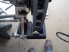
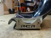
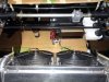
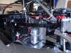
Re: Driver, footpeddles, & steering alignment. What did U do?
If you can see and reach everything well you will get used to any reasonable offset. I have owned factory cars with lots of offset and within a few weeks didn't think twice about it.
If you can see and reach everything well you will get used to any reasonable offset. I have owned factory cars with lots of offset and within a few weeks didn't think twice about it.
")
 ></o
></o