Dan's Build

Nice job. I finally got around to bleeding my brakes last week and had issues with leaks. Working the joints back and forth - tighten, loosen, tighten - is the only way to do it. Just don't take it too far, like I did. I split the end of one of the flared ends and didn't even notice it. Someone else spotted it. And I was blaming the fitting.

A.J.
 
Day 125

1. A quick picture of the final foot well brake line hookup. As I mentioned earlier, the transition from 3AN to 3/8x24 and back proved a challenge but was solved by a 3AN flex line.

2. A picture of the revised coolant line snaking around the fuel pump, fuel lines and brake/hydraulic lines to create as much separation as possible. Coolant line will receive insulation of course. May be hard to see, but I extended the 90 degree line and then made an "S" turn to get back over to connect with water pump on the other side of the wall.

3. Question. I have the 1999 Oldsmobile steering column (last picture). To have a steering column horn, do I need a clock spring? Does anyone have a part number if I do. The column came without one.

PS. Has anyone installed a C6 manual tilt/telescoping Corvette steering column?

Next endeavor is the coolant surge tank hookup/plumbing, AC plumbing and heater plumbing.....o boy.
 

Attachments

  • DSC02260.JPG
    DSC02260.JPG
    185 KB · Views: 429
  • DSC02262.JPG
    DSC02262.JPG
    199.7 KB · Views: 490
  • DSC02261.JPG
    DSC02261.JPG
    159.9 KB · Views: 445
Looks really good Dan, nice work.

I have the XLR steering column, so I can't be of much help there. I am a long ways off from worrying about the horn at this point. Havn't planned my set up yet.
 
Day 125


3. Question. I have the 1999 Oldsmobile steering column (last picture). To have a steering column horn, do I need a clock spring? Does anyone have a part number if I do. The column came without one.

PS. Has anyone installed a C6 manual tilt/telescoping Corvette steering column?

If you want to use a horn button on the wheel, and have it go through the column, you need the clock spring. Several of us, including me, have done this with the XLR column. It's the same theory with the Olds column.

An alternative is to use an aftermarket setup that has some kind of wired or wireless transmission to a receiver that can switch circuits as needed. Some of the fancier ones let you define the switch as momentary, latching, etc as needed.

I don't think anyone has used the C6 column- perhaps Ken has?
 

Ken Roberts

Supporter
"Bob from Cleveland" installed a Corvette manual steering column. http://www.gt40s.com/forum/slc-clubhouse/42886-lsa-slc-build-log-5.html#post466941

The C6 and XLR column are almost identical. There is only a slight difference in the wiper circuit wiring due to the fact the XLR had a rain sensing module. Bob still has his XLR column for sale.

As Will said....you do need the clock spring to use the horn. They should be fairly cheap at a wrecking yard as that was a very popular car (Olds Intrigue).
 
Checking it out Ken.

I'm toying with the NRG setup with a MOMO or Sparco flat bottom wheel with horn button built in.

Don't clock springs get old and wear out?
 
Checking it out Ken.


Don't clock springs get old and wear out?

I don't know if they wear out, but I can tell you from bitter experience (is there any other kind, really?) that if you have a clock spring mounted on the column and let it spin too far, it destroys the clock spring and you need to install another one... :(

Once I took the old, destroyed one apart for forensic analysis, it was apparent why this was so, at least with the XLR design- it's just a coil that is easy to over-rotate and tear off the small wires on the end.

Pro tip: take the clock spring off when you are building or playing with the car, and re-install it only when you are just about finished and have the steering column in and final-connected.
 

Mark B.

Supporter
Guys, you do NOT need the clock spring for horn on the Olds rack. I have the same rack on mine. It's completely different from the newer C6 / XLR rack. The clock spring on the Olds rack is just for the airbag and (I think) steering wheel controls. For the horn, you need the plunger connector that inserts in to the hole in the white plastic ring. It's this:
Ididit 2620000014, Ididit Installation Accessories | Ididit

I used that along with an NRG SRK-170H hub and one of their quick releases. Everything fit perfectly.
 
Mark

How did you ever figure that one out...very obscure for sure. To confirm, that spring wire fits into the white tube in the picture...correct?


Will this is worthy of the WIKI.
 

Attachments

  • DSC02263.JPG
    DSC02263.JPG
    176.4 KB · Views: 430
Mark

How did you ever figure that one out...very obscure for sure. To confirm, that spring wire fits into the white tube in the picture...correct?


Will this is worthy of the WIKI.

Yes, but I'm not sure I understand fully- perhaps Mark can elaborate. I see the horn wire in the link, but it looks like it needs to make contact mechanically, but I don't see how that happens. Does the adapter tilt to push the white plastic column to make the contact somehow?
 
Will

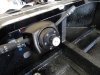
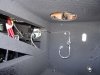
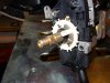
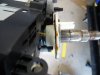
Being the curious sole that I am, I took it apart to see how it works. From the first picture, you can see a small brass plunger that comes out of the turn signal indicator. On the back side of the white ring, is a brass circular plate. Once the turn signal part is installed, that plunger engages the plate. The small wire that Mark found, is inserted into the white column on the steering wheel side of the white part which completes the circuit to the horn. The clock spring is not needed.

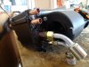
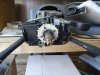
For those who have this column, I encourage you to clean the old grease and dielectric contacts since the grease is old and non functional. If anyone has taken the column completely apart to get at the bearings. I would like to know how you did it.

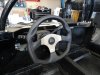
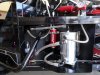
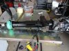
I spent a few minutes cleaning off surface rust and repainted the unit to spruce it up a bit.
 

Attachments

  • DSC02267.JPG
    DSC02267.JPG
    129.4 KB · Views: 426
  • DSC02268.JPG
    DSC02268.JPG
    190.4 KB · Views: 415

Mark B.

Supporter
Thanks Dan -- you saved me a lot of typing :)

The only reason I knew this was that I happened to be working on my previous '96 Corvette steering wheel when I started with the Olds column at the same time. It has exactly the same setup -- I was able to use those parts directly on the Olds column.
 
Day 133

1. Received the axles and install was straight forward.
<?xml:namespace prefix = "o" ns = "urn:schemas-microsoft-com<img src=" /><o:p></o:p>
2. Installed the NRG steering system (170H, 2.5 disconnect) in lieu of the supplied Grant system.I wanted/needed a flat bottom steering wheel for ingress/egress and a simpler way to wire a horn.NRG delivered.For those of you with the Oldsmobile steering column, you will not need a clock spring to mount a horn (thanks Mark).The way Olds configured the horn button back in the day was via a spring button located within the turn signal switches.It makes contact with a metallic ring on the back side of your steering column, hence no need for the clock spring.You will need to order the a wire (IDT-2620000014, Summit or Jegs).I have yet to validate the ground connection for the horn button but will in time.The pictures show how clean and simple the install, no welding, pinning or modifications required.It’s a total bolt on solution.
<o:p></o:p>
3. The AC system install has consumed a lot of time, as the evaporator is proving to be a space hog and needs some forethought. Since Vintage Air is now locating all the hose connections on the same side next to the bulkhead, it requires some modification to install and then figure out you plumbing layout (my schematic is below).The heater connections need to be cut back and a new bead made to secure the heater hoses as seen in the picture.The bigger issue is the two coolant lines and how to run them.I wanted to bend -8 and -10 lines using a tube bender and run them off the evap connections, but not being to find a shop that can make lines a bought premade straight tubing with fittings already attached.With a fitting already on, the bender could not bend close enough to the fitting to swing eh tube fast enough to clear the bulkhead wall.However, I have ordered two fittings from Cool Tubes, which are hard 90 degree angles which will immediately turn the coolant lines toward the floor and provide more space to experiment with a solid tube solution.Failing that, my solution is to use prefabbed 45’s for both the -8 and -10 lines and then plumb using rubber hosing (see picture).If you are using the factory interior tub, mark the locations along the side bulkhead it covers and also determine how much space behind the spider you will have to enter and exit the passenger side bulkhead.I will be entering and exiting the evaporator lines out the side passenger bulkhead just above the right passenger knee (top part of the side bulkhead).If you have the factory tub and the factory console, the console will need to be cut to allow for install around the evap unit as well.
<o:p></o:p>
4. Still waiting on parts to finish the engine coolant plumbing.The difficulty here has been finding fittings in either aluminum or stainless (plenty of brass out there), to minimize any differing metal reactions.Brass and aluminum are really not compatible metals.More to come on my plumbing solution soon.<o:p></o:p>
 

Attachments

  • DSC02296.JPG
    DSC02296.JPG
    195.7 KB · Views: 384
  • DSC02297.JPG
    DSC02297.JPG
    188.2 KB · Views: 437
  • DSC02294.JPG
    DSC02294.JPG
    171.8 KB · Views: 438
  • SLC AC Layout 2.jpg
    SLC AC Layout 2.jpg
    64.4 KB · Views: 387
Back
Top