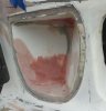
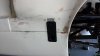
Thanks Richard. Already made a small change though. Didn't like the look of the aluminum blocks and deleted them. Everything else is as it was with just a new placement of the two supporting arms. The driver's side now has the top part of the Aerocatch 3 in place. Will work on the lower part next, then for the passenger side unless I pick up the transaxle and cable shifter this weekend and in that case I'll probably divert to it before getting to the other side to fix the other catch.

You are using an out of date browser. It may not display this or other websites correctly.
You should upgrade or use an alternative browser.
You should upgrade or use an alternative browser.
Darrin's MMR BOSS based GT40
- Thread starter darrinps
- Start date
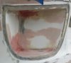
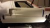
Driver's side latch installed. It's one of the Aerocatch 3 pieces. Had to reinforce the fiberglass a bit, then epoxy the back plate in place for good measure. The other latch is a Hartwell I am thinking about for the top to keep it snapped down into place. I have four of them looking for a use.
Attachments
Last edited:
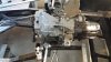
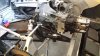
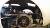
Test fitting the Audi 01E. Need to notch out about 1/8" in two places on the stainless cross member holding the clip if I need to move the transaxle aft much (it has slotted holes in the brackets).
Attachments
Looking good Darrin. Sam, John and I need to come by some weekend to take a peek...
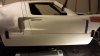
Have the passenger's (left hand drive so on the right for you folks elsewhere) side Aerocatch 3's in place now. Test fitted the door while I was doing that. From what I have read, I guess I can't complain as it was pretty close to being where it should be fitting wise. The tape on the door was there as a guide for me to trim about 1/8" off to give the thing room to open. It fit, but was a bit too tight.
Attachments
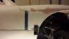
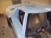
The step between 'A' pillar and door, I've put a red line on your picture to show what I mean and in comparison someone elses car. It should be flush.
Now that might just be because your doors aren't hanging atm but just placed but the body work fitting gives a dimension across the door with IIRC about 2cm range, if you're at the minimum worth trying to move the front forwards a bit as it'll reduce the 'step'.
Now that might just be because your doors aren't hanging atm but just placed but the body work fitting gives a dimension across the door with IIRC about 2cm range, if you're at the minimum worth trying to move the front forwards a bit as it'll reduce the 'step'.
Attachments
The step between 'A' pillar and door, I've put a red line on your picture to show what I mean and in comparison someone elses car. It should be flush.
Now that might just be because your doors aren't hanging atm but just placed but the body work fitting gives a dimension across the door with IIRC about 2cm range, if you're at the minimum worth trying to move the front forwards a bit as it'll reduce the 'step'.
It's hard to see in my photos, but mine looks almost exactly like the example you gave if I am understanding what you are concerned about.
The front edge of the doors (just ahead of the glass...where the red marker is) line up closely with the spider.
Ian Anderson
Lifetime Supporter
When you are doing all this should you not have the door rubbers fitted?
they will "move" the final sealing position of the door
Ian
they will "move" the final sealing position of the door
Ian
When you are doing all this should you not have the door rubbers fitted?
they will "move" the final sealing position of the door
Ian
Yes, and they are Ian.
It might just be because the door isn't located properly yet (it looks a bit down at the top right) or it might just be an optical illusion from the photo. Can be quite hard to tell from photos sometimes. As long as you're happy with it in the flesh.")
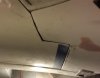
The only thing that concerns me from what I can see in person is that the top of the door sits a bit below the roof line at the back. The front sits about where it should. The seals are already in place.
Not sure what to do about the top of the door just yet. It's down at least 1/4" if not 3/8".
Hi Darrin:
Did your kit include the body alignment dowels and bushings? Looks like the gap from the sill cover to the front and rear clips is a bit tight. Also in the drawing I got with my body from FRP guy shows a 1/2" gap between the chassis side pod and the rear legs of the roof spider. This allows the fiberglass sill cover to slide in and be mounted.
Did your kit include the body alignment dowels and bushings? Looks like the gap from the sill cover to the front and rear clips is a bit tight. Also in the drawing I got with my body from FRP guy shows a 1/2" gap between the chassis side pod and the rear legs of the roof spider. This allows the fiberglass sill cover to slide in and be mounted.
Hi Darrin:
Did your kit include the body alignment dowels and bushings? Looks like the gap from the sill cover to the front and rear clips is a bit tight. Also in the drawing I got with my body from FRP guy shows a 1/2" gap between the chassis side pod and the rear legs of the roof spider. This allows the fiberglass sill cover to slide in and be mounted.
It did not (I purchased them from Cushman I believe it was). The spider's rear pillars are resting on washers to bring them up to the needed height so the sill cover can slip under. Personally, I think 1/2" is too much play. I can't recall what my manufacturer specified, but I know it was less than that.
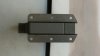
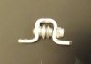
Nominated in the "overkill" category (and I know I'm not alone in going there with many parts we use on these cars), here is a part I made as a guide for the parking brake cables. The body is made out of 304 stainless, 3/4" wide by 1/8" thick. The bolt, washers, and locking nut are also stainless. Inside is a V groove sealed ball bearing roller. The base is drilled out to accept 5/32" rivets. I'll mount these to guide the cable instead of having it rub across something.
Attachments
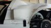
Wheels FINALLY made it in after 12 weeks. Looks like I may need to flare my rear fenders a bit. Fronts look good but I think I am going to try to squeeze one size larger tire in as the wheel is wider than I like for the tire and it looks like it will fit. Will be going to a 245/40/18. 235/40/18 there now.
The rears are 305/35/18 and seem to fit well (save they are a bit too wide) although I think the suspension isn't set right at the moment to see everything for sure.
The rears are 305/35/18 and seem to fit well (save they are a bit too wide) although I think the suspension isn't set right at the moment to see everything for sure.
Attachments
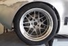
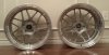
Here is a close up of the wheels in case others looking in the future want to know of some options.
They are Forgestar F14F 2 piece modulars. The sizes are specific to my build. If I had it to do over again I'd make the rears 20mm more backspace (less negative) as I might need to flair the rear fenders a bit to have it all fit.
Front: 18" x 9.5" at -2 offset. These weigh in at 23.6 pounds (lite)
Rear: 18" x 11 at -30 offset. These weigh in at 25.1 pounds (very lite)
Only downside is that these things took TWELVE weeks to get them made.