Dean's GT-R build thread

Dr. David

Lifetime Supporter
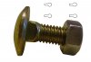
What happened to the rivnut in this discussion......did I miss something?

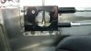
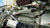
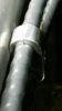
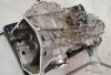
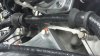
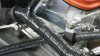
I mounted my shifter with steel Rivnuts and, in my application, (LMP-1) it is solid as a rock. I fabricated aluminum brackets out of 1.5" X 3/16" angle, which are bolted solid to the shifter box, and in turn bolted to the side panel with seven 5/16" bolts through the steel rivnuts.

The brackets could be classified as "billet," which of course adds more horsepower. :laugh:

The side panel is constructed of some fairly thick and solid sheeting, and of course you don't actually "slam through the gears" anyway if you are a good driver. However, I feels like it could take a real beating.

Perhaps the aluminum brackets could be extended or modified, or taken to an aluminum welder, for other applications.

I'm no expert,....... just how I did it for my application, but for me the hardest part was getting a shifter that had a reverse lock-out in the proper location!

David
 

Attachments

  • 20160501_174414_resized_1.jpg
    20160501_174414_resized_1.jpg
    215.2 KB · Views: 627

Dr. David

Lifetime Supporter
This is an incredible build log Dean!....There is so much here to learn from your expertise!

Just another idea:
For those of you that feel heat may be a problem for the shifter cables, there is a black vulcan fire sleeve that is available that is supposed to help in high-heat situations, such as through the engine compartment. The black almost looks like the shifter cable. It is lined with braided fiberglass and is reportedly heat resistant to 500 degrees of continuous temp. I got mine from Performance Plus on eBay, covered the shifter cables from the bulkhead to the shifter on the transaxle, and wrapped the ends with aluminum high-heat tape......"so the fiberglass won't leak out." :blank:

Again, no expert, just an idea.

David
 

Attachments

  • 20160501_194057_resized.jpg
    20160501_194057_resized.jpg
    249.3 KB · Views: 541

Dr. David

Lifetime Supporter
Line clamps for shifter cables through the cockpit:...or through the engine compartment......Earls 167207.
Adel clamps are so much cheaper and function just as well, but aluminum line clamps may be a little easier to deal with in very tight quarters.....or not.

Thanks again Dean for your great contributions to this forum!
David
 

Attachments

  • 20160501_174631_resized.jpg
    20160501_174631_resized.jpg
    36.4 KB · Views: 459
There are a lot of great ideas here! I am going to pull the inspection plate off the front of the tunnel and look at the clearance on the sides and the 45 deg. part of the tunnel. I was reviewing some older pictures and, although I don't have any measurable clearance on top, I might have some on the sides and the angled area.

If that is the case, I think I will try a 2 inch wide steel strap in front and behind the shifter with nit rivets. I'll post up some pictures tonight.

David, I ordered the cable sleeves today. The gold reflective tape is already coming loose on the cables. Those sleeves will be a much better solution. Thanks!
 
'Nit' rivets are probably an appropriate term..
Consider this for another nitwit idea! drill 4 holes to accept coach bolt head and slots to accept square shank... end of slot to be where bolt holes in shifter base would be in normal bolt/hole situation.
 

Attachments

  • m8-x-20mm-cup-square-bolt-nut-3604-p.jpg
    m8-x-20mm-cup-square-bolt-nut-3604-p.jpg
    116.6 KB · Views: 347
'Nit' rivets are probably an appropriate term..
Consider this for another nitwit idea! drill 4 holes to accept coach bolt head and slots to accept square shank... end of slot to be where bolt holes in shifter base would be in normal bolt/hole situation.

That was the nitwit point I was trying to get across in my earlier posts. Thank you for making it much clearer to understand. I think it would work great in this application.
 
So here is what I decided to do about the shifter. I sat in the car and shifted the gears just trying to get an honest feel for how much force there will be. It's not that bad. The Graziano box actually shifts pretty smooth. I don't think I will need a giant saddle to hold this in place. Also, I did a thorough inspection of the tunnel and the tank and the area in between. There is simply no room for a carriage bolt head or a nut rivet or any type of fastener with any type of head. As I was drilling through the tunnel I had to go very slow to "feel" the gap between the tunnel and the tank. There is barely room for a pop rivet to grab completely.

So I decided to add a steel plate to the tunnel with rivets and epoxy. I am using a 6 in wide by 10 inch long 3/16 steel plate. I drilled 4 holes to bolt the shift box to this plate and recessed the holes. I ran the bolts through and tightened the nuts.


I welded them in place and ground them smooth.


Then I drilled a bunch of holes. Yeah, that's probably overkill but that's how it goes!


Then I drilled the holes in the tunnel and scuffed the surfaces and cleaned them with acetone.


I painted the top of the plate black and tested the fit.


I used Loctite metal epoxy to bond the plate to the tunnel. I used the whole tube.


I covered the tunnel with the epoxy and put a wood block over the studs then I sat a 75 lb steel bar on the plate. After a few minutes I riveted the plate to the tunnel. It sat here over night.


This is what it looks like today all bolted in.


Thanks for all the suggestions.
 

Dr. David

Lifetime Supporter
That looks great Dean....Rock Solid!
Perhaps the factory can use your design to fabricate and tig-weld a bracket onto future chassis..... for all of us who are Tig-challenged.....or else everyone can copy this great technique.
 
So here is what I decided to do about the shifter. I sat in the car and shifted the gears just trying to get an honest feel for how much force there will be. It's not that bad. The Graziano box actually shifts pretty smooth. I don't think I will need a giant saddle to hold this in place. Also, I did a thorough inspection of the tunnel and the tank and the area in between. There is simply no room for a carriage bolt head or a nut rivet or any type of fastener with any type of head. As I was drilling through the tunnel I had to go very slow to "feel" the gap between the tunnel and the tank. There is barely room for a pop rivet to grab completely.

So I decided to add a steel plate to the tunnel with rivets and epoxy. I am using a 6 in wide by 10 inch long 3/16 steel plate. I drilled 4 holes to bolt the shift box to this plate and recessed the holes. I ran the bolts through and tightened the nuts.


I welded them in place and ground them smooth.


Then I drilled a bunch of holes. Yeah, that's probably overkill but that's how it goes!


Then I drilled the holes in the tunnel and scuffed the surfaces and cleaned them with acetone.


I painted the top of the plate black and tested the fit.


I used Loctite metal epoxy to bond the plate to the tunnel. I used the whole tube.


I covered the tunnel with the epoxy and put a wood block over the studs then I sat a 75 lb steel bar on the plate. After a few minutes I riveted the plate to the tunnel. It sat here over night.


This is what it looks like today all bolted in.


Thanks for all the suggestions.

My want to think about drilling blind some holes in the bottom of the plate for the epoxy to grab hold of during cure time. Using a disc sander with a abrasive disc with a cross hatch pattern works well also.
 
I did get quite a bit done this weekend but I'm still organizing my pictures and my thoughts. Here are a few things until I get better organized.

I put the axles in. This isn't rocket science but I wanted to share that I there are 2 different ends on the axles. The sealed end I put at the wheel and the open end with the exposed grease I installed at the gear box.


One axle is short than the other but you can figure that out.


Fran Hall RCR

GT40s Sponsor
It's the design of the transaxle itself as the diff is offset
The crank centerline and the input shaft have to be inline so it's nothing to do with the trans location
 
The R&P and diff offset is due to the trans requiring space for the AWD system in original applications which can be seen in this gear train pic and in the bell housing of trans pic. Both pix from Mr Google..
 

Attachments

  • Audi-R8-Grey-Removal-Of-Gearbox-For-Turbocharger-Upgrade-Ramspeed-Automotive-2.jpg
    Audi-R8-Grey-Removal-Of-Gearbox-For-Turbocharger-Upgrade-Ramspeed-Automotive-2.jpg
    366.9 KB · Views: 399
  • innovative-new-transmission-from-graziano-revealed-73159-7.jpg
    innovative-new-transmission-from-graziano-revealed-73159-7.jpg
    57.3 KB · Views: 404
When I installed my shift cables I wrapped them with that gold DEI foil. Well, it is already coming off. So I ordered these high heat sleeves with fiberglass lining that David suggested. I ordered them off of Ebay. There are quite a few venders that sell them. I used this type of sleeve on my GT40 and it worked great so I pulled off the gold foil and ran each shift cable through a 3ft long piece of this material.


This should keep the heat from the headers away from my cables.


Thanks for the tip David!
 

Dr. David

Lifetime Supporter
Heat is an Enemy.......Dean, you probably are well aware of these other tricks as well:

1. I use Aeroquip Starlite hose and fittings for my fuel, oil, and transmission lines. For the fuel line that runs from the fuel regulator to the intake, I use DEI Heat Sheath for added insurance and protection from the exhaust and engine.

2. Starter Heat shield, as well as a Heat Sheath on the starter cables,..... similar to the factory loom lines for the adjacent sensors. Black ceramic for the exhaust system,.....(not as pretty, but supposedly has the most heat protection),..... and zip-ties with stainless steel tabs on the entire car.

3 & 4. Wire loom Insulation, ....using spacers for stand-offs,.... for the loom as it attaches to the engine on the back of an LS3.....(no insulation on the shifter cable in photo 4 which is coated with the high-heat sleeve mentioned by Dean above). Protect your wires!

I just made this up: "If you wouldn't touch it after it has been running hard, why would you expect heat-sensitive materials to put up with it for the long haul?
I am certainly not an expert and I accept criticism, but please don't hijack this great thread.

Looking forward to the rest of your build Dean!

David
 

Attachments

  • 20160510_205422_resized.jpg
    20160510_205422_resized.jpg
    256.7 KB · Views: 415
  • 20160510_205157_resized.jpg
    20160510_205157_resized.jpg
    181.8 KB · Views: 363
  • 20160510_204953_resized.jpg
    20160510_204953_resized.jpg
    185 KB · Views: 361
  • 20160510_205041_resized.jpg
    20160510_205041_resized.jpg
    175.2 KB · Views: 412
Allan and I did the same thing (sleeving my shifter cables with those high temp sleeves AND a reflective foil on top) and the shifter cable still melted because of it's close proximity to my headers. Quickly.

So even if you do this, and I still advocate doing it, be careful to route the shifter cables so they are as far away from the headers as possible. Several inches I think would be best.
 
Do you think a double layer of that sleeve material would make a measurable difference? I don't see the headers being 500 degrees 18 inches from the heads which is the max temp rating but if it would help I would double up. I have a smaller sizr for my throttle cable that might fit inside the shift cable sleeve. I could also wrap the area in gold foil.
 
Back
Top