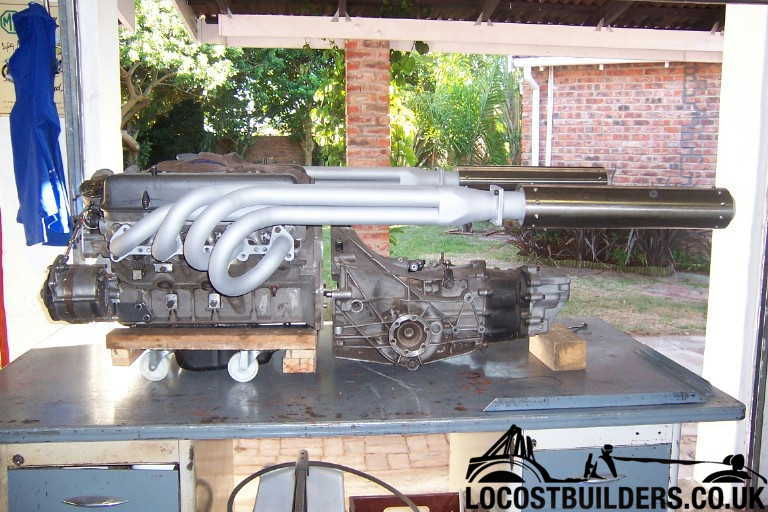
Exhaust query?

Dave Bilyk

Dave Bilyk
Supporter
Great picture Lynn,
can I pick up on the 'pull back of the piston' you mentioned and say that I think that this and valve overlap are the key things.
First, I think that reversion occurs only at low revs. Tuned lengths come into play at higher revs where the combustion cycle matches the wave reflection time. At low revs this isnt happening because the negative pressure wave has already been and gone, so I feel that tuned lengths and positive / negative pressure waves are not key.

What I think is important is the valve overlap. For a mild cam, the overlap is small, and so the exhaust valve closes before the piston has chance to draw back any exhaust, so this engine will tick over happily at low revs, have good throttle response at low revs, and accept full throttle right away.
For a hot cam, the overlap is much larger, and at low revs the exhaust valve stays open long enough for exhaust gas to flow back into the cylinder on the induction stroke. This results in the need for a higher rpm tick over, gives poor throttle response at low revs, and sometimes a tendency to spit back on full throttle low revs because of mixing of hot exhaust gas with incoming charge.

So, what I think the reversion cones do, is, by increasing local gas velocity, they put a little more kinetic energy into the gas which helps to move the onset of reversion a little higher in revs.
Also if there is any recirculation / backflow near the wall of the pipe, the cone will help to block it.

At higher revs the inertia of the higher exhaust gas velocities helps to draw in charge during the overlap period, and this is enhanced when the exhaust length is tuned to the revs and a negative reflected pressure wave arrives during the overlap period to assist.

That's the deal as I see it, if I have understood it correctly. Guys please pull me up if you think that I am talking about a different effect or have misunderstood something.
 
Sorry Lynn ! but jet engines, (like the low by-pass turbojet you have pictured running in A/B) DON'T "pulse" like a reciprocating engine does in its exhaust system. Aircraft gas turbines, generally speaking, will only exhibit what you are talking about when the bleed valve on the commpressor has a malfunction. Preventing excess air from the compressor from causing an aerodynamic stall inside the engine. What you are seeing in that awesome picture is just the beautiful supersonic flow of burning kerosene ! There is no reversion happening. Also aircraft piston engines spend the vast majority of the operating life a small RPM range (high power settings) so they respond well to the a/r cones currently being discussed
;)
S
 
Bloody Hell !!! With all this technical stuff going on way over my head, I think I'm drowning. lovely picture though Lynn!!
 
Last edited:

Lynn Larsen

Lynn Larsen
Scott, the picture was only to depict the pressure pulse wave form. It was the only thing I could think of that graphically displayed the overall notion that pressure flows form in waves with a sinus rhythm, whether it is a jet exhaust, an irrigation pump, and engine exhaust (or intake for that matter), although each case will have its own natural frequency. It's basic fluid dynamics.

I was never describing what was happening inside the jet engine, but, I beg to differ with you on the visual part of the exhaust in the picture: IT IS A FLOW EXHIBITING A SINUSOIDIAL WAVE PATTERN. Why else do you think there are various, and rythmic, densities seen in the exhaust gasses?

Please believe what ever you want to believe, but I didn't pull this stuff out of my butt.

Lynn
 
Well I'm no rocket scientist, just a lowly jet mechanic, but lets see if I can take a stab at it ... as the exhaust gas stream cools and expands behind the tailpipe there is an energy and velocity loss causing the blue "discs" you see in the picture, thats why they get progressivly smaller behind the engine. But the change is constantly decreasing not alternating up and down, as you would suggest in the sinusoidial ( read A/C current ) pattern.
Much respect and regards,
Scott
rockonsmile
 

Dave Bilyk

Dave Bilyk
Supporter
Scott,
I dont think you really have a disagreement here. There are two patterns in the exhaust, Lynn focused on one as an example and you focused on the other. What we see in the jet exhaust is a shock wave pattern in a supersonic stream, everything inside the tapering stream is supersonic, everything outside is subsonic. As the gas at the outside of the supersonic stream interacts with the atmosphere and gives up energy it becomes subsonic and mixes with the atmosphere in an expanding plume that the picture doesnt show. So the supersonic stream tapers away linearly (Scott) until it disappears and all the efflux is subsonic.
Lynn was using the visible shock waves in the stream as an example of the sinusoidal standing wave patterns / reflections that occur in pipes and that seems perfectly valid to me, and an awesome way of visibly showing it without a pipe wall to get in the way.
 

Lynn Larsen

Lynn Larsen
Thanks, Dave.

Scott, one of the basic characteristics of a sinusoidal wave pattern in nature (as opposed to the ideal or where it encounters no opposing forces) is that it is a decaying wave pattern. And, in terms of an "up and down" sinus rhythm, you didn't read my intial post very closely I take it; for in it, I described the pulse pattern as a 3 dimensional sinusoidal pattern (take your flat sinus curve and spin it about its central axis - the swept area would be a 3D sinusoidal wave.) As another visual of what I mean, imagine a long childs balloon (like the ones they make balloon animals with), now at regular intervals put a small rubber band around the balloon. The result would be a 3D sinusoidal model. (A series of American footballs, end to end, also comes to mind.) Get the picture?

Unfortunately, this discussion has become centered on the graphical model used to try to explain why cones in the exhaust can be helpful, rather than on why the cones are helpful. Without cones, backflow gasses (reversion) leaking into the lower presssure areas between the pulses, cause increased turbulence in these areas which tends to act as a brake against the higher pressure and higher flow areas, which can increase reversion.....and so on. Unchecked this cycle will finally reach a balance, but it will end up with a highly restricted out flow. The cones act to dam this back flow, thereby lessening the braking action and breaking the cycle. The trick of course, is to properly size and shape the cones to have minimal effect on top end performance, while providing enough control at lower RPMs to maintain effecient operation. To use your example, Scott, of A/C current I am guessing that the diameter of the opening will be around the RMS (root mean square), or its 3D analog (I am reaching the limits of my recall), of a sinus wave with a wave length of that found at optimal performance and an amplitude of the exhaust pipe's diameter. I would also guess that the taper would coorespond to the slope of a line tangent to wave at the RMS point. Not having studied this phenomenon, I am only guessing, but feel sure that this would be a good starting point, at least.

Lynn
 

Keith

Moderator
llarsen said:
Thanks, Dave.

Scott, one of the basic characteristics of a sinusoidal wave pattern in nature (as opposed to the ideal or where it encounters no opposing forces) is that it is a decaying wave pattern. And, in terms of an "up and down" sinus rhythm, you didn't read my intial post very closely I take it; for in it, I described the pulse pattern as a 3 dimensional sinusoidal pattern (take your flat sinus curve and spin it about its central axis - the swept area would be a 3D sinusoidal wave.) As another visual of what I mean, imagine a long childs balloon (like the ones they make balloon animals with), now at regular intervals put a small rubber band around the balloon. The result would be a 3D sinusoidal model. (A series of American footballs, end to end, also comes to mind.) Get the picture?

Unfortunately, this discussion has become centered on the graphical model used to try to explain why cones in the exhaust can be helpful, rather than on why the cones are helpful. Without cones, backflow gasses (reversion) leaking into the lower presssure areas between the pulses, cause increased turbulence in these areas which tends to act as a brake against the higher pressure and higher flow areas, which can increase reversion.....and so on. Unchecked this cycle will finally reach a balance, but it will end up with a highly restricted out flow. The cones act to dam this back flow, thereby lessening the braking action and breaking the cycle. The trick of course, is to properly size and shape the cones to have minimal effect on top end performance, while providing enough control at lower RPMs to maintain effecient operation. To use your example, Scott, of A/C current I am guessing that the diameter of the opening will be around the RMS (root mean square), or its 3D analog (I am reaching the limits of my recall), of a sinus wave with a wave length of that found at optimal performance and an amplitude of the exhaust pipe's diameter. I would also guess that the taper would coorespond to the slope of a line tangent to wave at the RMS point. Not having studied this phenomenon, I am only guessing, but feel sure that this would be a good starting point, at least.

Lynn

yeah, but is it LOUD? :confused:
 
I have just built a set of headers and exhuast system for the McLaren M8B replica that runs 1 and 5/8ths pipe, 4 into 1 with 2 1/2 system and straight thru mufflers. My question is what sort of restriction would I need for back pressure? The motor is a Rover / Buick 3.5ltr V8 running 4 twin choke Del Orto`s and a mild cam. The car is not being built as a race car but will get a bit of stick on track days.
 
Russell,

I would suggest the 'Flowmaster' type mufflers, with these you dont need to create a restriction by way of reducing pipe dia etc, and since you have built your own headers etc you may wish to have a go at constructing your own. If not they are available from most performance outlets like ;pioneer equipment- sedgedins-performance parts etc.

Obviously there are many other makes/designs out there which also work well, but I have found that the principle the Flowmaster works on is fairly easy to configure into a tight space with a bit of lateral thinking and does not kill a lot of power ( If any ) in the process.

Jac Mac
 
Jac
I tried to fit those but could not due to space restriction, so had to run the in line tube type. I was looking for some indication of what if any back pressure was needed.
Cheers and I hope you are not freezing down there.
 
Hope harder Russell, looks like another good one tonite.

I incorporate the tuned length of the tailpipe within the muffler case in a situation like yours- typical 'muffler' built along these lines would be 15" long-12" to 14" wide-3"to 4" deep. Can be fitted in any position.

Better go put another tree on the fire!

Jac Mac
 
I already have the full system built with the correct lengths fitted, how ever the subject of or lack of back pressure was raised so thats why I was hoping there would be loads of helpful advice just waiting to be thrown at me. It might end up a suck it and see job.
Cheers
 

Russ Noble

GT40s Supporter
Lifetime Supporter
Back pressure Russell?

Forget it! Your 'correct length' pipes are designed to provide negative back pressure at the valve at the revs that they are designed to work at. However at other revs you do get 'back pressure' and that is what the anti reversion cones that are the subject of this thread are designed to reduce.

Ideally you want negative pressure at the back of the valve to assist scavenging, particularly during the valve overlap phase. The notion of needing positive pressure in the exhaust system was laid to rest 50 yrs ago. Hope that helps.

Cheers
 
Hi Russel - Nice to see someone else using a rover in a Canam style car. I made these headers and silencers for my T70 inspired project

Detail in this thread http://www.gt40s.com/forum/lola-t70-lounge/21437-t70-style-headers.html

Cheers

Fred W B

3exhaust2.jpg
 
They look like the right noise, at least it looks like you have more space as they run straight out the back. mine have had to go a little forward then down back up over the axle crossing the gear box to the other side then out lower than the box itself. That looks like an Audi box also, what model have you used.
Cheers
 
Back
Top