Ford F3L and David Piper

you might just be a god.... I would like to have 50% of your skills, and then i would be happy. I am doing som 3d cad work of myself but my work is on beginners level.

:D Tobias, don't overact, everybody has to start from the beginning!
I also started with cylinders, blocks and assemblies, but the years taught me how to do the other stuff as well..
 
...the last few days i found some time to finish the surface model of the monocoque. Next step: identify wallthicknesses for minimal mass at given constraints.
 

Attachments

  • Fortschritt_100214_02.jpg
    Fortschritt_100214_02.jpg
    39.1 KB · Views: 963
..in the mean time I created part of the parameterized FE-model. In this picture you can see the connectors (mainly rivets) and the wallthickness groups. At the moment I am meshing, I'll post some more pictures when I'm done.
 

Attachments

  • Fortschritt_100218.jpg
    Fortschritt_100218.jpg
    54.7 KB · Views: 907
..it took me the last few days to mesh the surface model and incorporate the connectors (rivets) into the FE-model. Well, now the geometry is discretized, and the next step is to extend the simple FE-model to an optimization task. I hope I can start the first run this weekend.
 

Attachments

  • Fortschritt_100226.jpg
    Fortschritt_100226.jpg
    55.7 KB · Views: 748
@Olivier: Thanks a lot. Modeling the rivets and meshing took me all in all about a week (during the evenings), which gives approx. 25 working hours. This number includes surface cleanup, organizing collectors, meshing, connector creation/realization. To get a running optimization you have to add approx. 30 hours (these numbers are, of course 'measured' in my working speed, don't know if that's fast or slow) for designvariables, designrelations, responses, loads, constraints, load cases and rigids. Well, and after that take another 20 hours for debugging and troubleshooting till the thing gives some good results (this is where I am now).
I'm gonna post some pictures in the next few days, when my computer isn't so busy any more ;-)

@David: :D thanks a lot for the compliment, but I think this is (I have to try to translate the german saying) 'a legague above me'. :D
 
..well, after quite some calculation time the discrete optimization of the monocoque is done. I have made a parametric study of weight vs. constrained torsional stiffness and did some fine adjustments on the choosen final design.
To give some numbers: For the ease of manufacture and robustness of some unconstrained regions I have decided not to squeeze every kilogramm out of the optimization. The result is a very robust and stiff structure, having a torsional stiffness (roof structure and windscreen not taken into account yet (!)) of l.b. 12000Nm/deg and u.b. 16850Nm/deg and a weight of 94.5kg. I have to mention that the stresses due to the load collective are kept so low that damage tolerant aluminum alloy can be used (thats what some extra kilograms are caused by).
Attatched some pictures from the two torsional stiffnes load cases.
Now I can start to work on the patterns for lasercutting of the sheets.
 

Attachments

  • Fortschritt_100311_01.jpg
    Fortschritt_100311_01.jpg
    46.2 KB · Views: 672
  • Fortschritt_100311_02.jpg
    Fortschritt_100311_02.jpg
    47.9 KB · Views: 667
Leo,
Those are pretty good numbers. More than strong enough. Is the whole tub going to be aluminum or a combination of carbon and aluminum?.
Dave
 
Hi David,
the only materials involved are aluminum and steel sheet metal (at the suspension pickup points). The aluminum necessary doesn't have to be heat treated high strength quality, which gives huge benefits in terms of lifetime (these are damage tolerant, means they have better fatigue strength than e.g. 2024T6 or 7075T6). Also it makes the whole thing more corrosion resistant and cheaper, which is no necessity, but nice.
 
Leo,
How are you going to cut all of your panels? Do you have a 2-axis machine with water jet or small electric robot. All the CAM files from the Catia would make short work of it. It would even punch all of the rivet holes for the panels. Your tub will better than the original.
Dave
 
Hi Dave,

we will have all the panels laser cut. The plan was to include most of the rivet holes during this process for indexing the panels to each other after bending. The only precision factor left to be aware of in the chain of manufacture is the process of unwinding the sheets from the 3D design down to the cutting plans. I have to figure out the k-factor of the sheets and the bending process I will use in order to determine the deviation of the length of the unwind bend in comparison to the theoretical length of the centerline. This will ensure a tight and perfect fit without the necessity for a very complex building jig.

..and thanks a lot for the comparison to the original. ;-)
I came across a stiffness value of the HonkerII tub a little time ago and could see that Len Baileys tub designs were very lightweight but also soft from the stiffness point of view. As you know, this is good for the final weight of the car but makes it much more difficult to drive, due to the severe flexing under racing loads. So in the end you win nothing by neglecting the stiffness issue. Well and as the Honker and the F3L monocoque were built quite at the same time by the samme designer I suppose the original F3L monocoque doesn't possess a huge stiffness either. But as there are no numbers available, this is left uncertain.
Well, I am sure about my numbers and torsional stiffness is e.g. more than twice the value of the Porsche 917 frame (I could find numbers between 5000 and 6000Nm/deg), with still a very good weight and so I am quite happy with my design.
 
Last edited:
Leo,

I've seen laser used on steel but not on aluminum. I was just wondering what kind of distortion you would get from the heat generated cuting the thin aluminum and what kind of edge. Water Jet would not generate any heat and the edge would be a tad rough but barely noticable.
Dave
 
Hi Dave,

yes, you are absoluteley right, I am aware of the distortion that is possible in course of laser cutting. We were planning to do the very long and thin parts by waterjet (which is a little more expensive judged by the quote that I have), because they are endangered to distort. The other parts which are more or less stiff souldn't be a problem in terms of distortion, so I've been told. The heat influenced zone is really small, so I think we should be safe.
Thanks for the comment
 
..some news from the fabrication side:
Apart from paint, die segments and hydraulic lines the bending press is done.
It is surely not a real beauty, but it will do the job it is intended for :D
 

Attachments

  • IMGP1940.jpg
    IMGP1940.jpg
    26.4 KB · Views: 886
  • IMGP1942.JPG
    IMGP1942.JPG
    36.7 KB · Views: 807
  • IMGP1944.JPG
    IMGP1944.JPG
    54.9 KB · Views: 756
  • IMGP1946.jpg
    IMGP1946.jpg
    24.4 KB · Views: 825
  • IMGP1947.JPG
    IMGP1947.JPG
    50.8 KB · Views: 908
Sir, is this a one off build or will you consider the commercial aspects of what you are doing? I know this car is not a great road car but with some slight modifications it would be possible. I know you have allot on your mind but as a big fan of what you are doing I can only dream that this is not the end when you are finished with this work of art.
 
Insane!

Leopold, what are those holes made for?

Just a quick question, in your chassis design, did you used complex shaped pararts (stamping parts) or did you used "only" flat sheet folded?

I've been desperately searching how to design "complex" shaped parts with CATIA, but didn't even managed to make a flange on a curved part with the sheetmetal workshop. I know there is a aeronotical sheetmetal workshop, but I havn't it...

Thanks for sharing.

Regards

Olivier.
 
Hi gents,

thanks for the questions.
@Rhygin:
Thanks a lot for your nice input. I've been asked this question quite a few times now. To tell you the truth, we do not depend on selling anything. The financing of this project is completely done by me and my father, but keep in mind that the money is not the problem. Not because we have so much, but because we make nearly everything by ourselves. The problem is the time needed to do all this. Both of us have a regular job which keeps us busy anyway and all the other spare time goes in the F3L. That isn't fun all the time, I think you can imagine. But on the other hand we have reached a level now, where there is no return. Well, a return wasn't to be considered anyway ;-).
To answer your question:
We will maybe produce a very very limited number of F3Ls (to be counted on one hand). IF:
There will be a customer willing to pay, and the thing is not gonna be cheap. Not because we just want to deal with rich people, but because I can't give away 5 years of my life and the best engineering I am capable of for a few bucks.
I hope that answers your question. I hope this is not kind of a disappointment for you but I think you will understand, even if it is.

@Olivier:
The holes as well as the strange contour of the upper die are topology optimized to produce the same displacement on the upper part of the tool as well as on the lower part of it. This will ensure that the bent part has the same angle everywhere along the bend (constant gap). It was kind of a problem to design this as there are a lot of casess to be covered, bending on the full left, on the full right, different lengths and so on.
I have tried hard to use just folds, as you say to make manufacturabilty as easy as possible. For 3D shaped parts you have to work a lot with the english wheel or a stretching/bulging tool OR you make a pressing tool which is nonsense as we are not going to produce several hundred pieces. Those parts mentioned are also from a structural point of view not really efficient. That is why they are usually used for body segments (like the GT40 roof), where you have to match the body shape. Anywhere else it wouldn't make much sense to use shapes like this.
Design of parts like this is not easy in catia, as it is based on freeform surfaces. But as always, you just have to try hard, everything is possible.
 
Hi Leopold!

Thanks again to take the time to answer my dummy's questions...
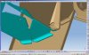
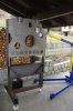
If I understand well, your press is designed to optimize deformation of itselfs in several cases of bending?
Wow! IF I had to design a press, I wouldn't have considered this problem at all! I would have just used a "consistant" thickness of steel, and nothing else... Really, really interesting to learn all this "little" tricks from you reading this post!

Concerning stamped parts, I'm not totally agree with you. If you have a part stressed in a non linear way, increasing, decreasing, increasing i.e, can"t it be usefull to apply to this part a shape that comply with the actual stress, with progressives sections that give the correct stiffness @ the right point? (In my mind, that is the principle advantage of using composites on a mono)
If you look close a gt40 chassis, there are a LOT of pressed parts, floor, rear bulkhead, lower front suspension ribs..., and that makes me wonder how gox, mirage and others arrive to produce those parts, without very expensives tools...

Bu the way, don't you need to adopt a brother?

Cheers

Olivier.
 
Back
Top