Big milestone today.
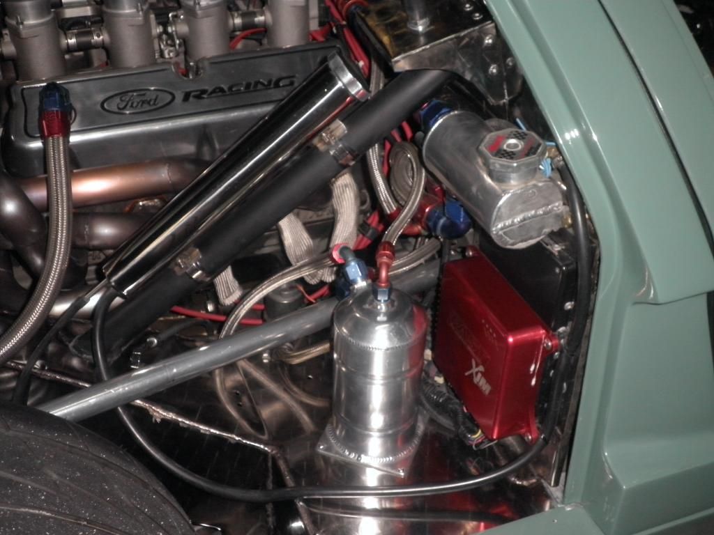
Fireup the engine

epper:
Besides a small water leak still to pinpoint, nothing major.
It runs silk smooth so the engine balancing really paid off.
It picks up very well on the throttle.
After 5 minutes I noticed the water temperature rising rapidly and started to boil coolant at the reservoir while I felt the radiator was still cold. So shut it off immediately.
The only thing I can think off is that the new thermostat is not opening properly.
The waterpump is an Edelbrock Victor 8843 standard rotation.
Other suggestions always welcome,
I heard a lot of people remove the thermostat with their Gt40's ...;O)
Could it be that the resistance from the radiator together with the too long pipes causes a very weak flow...not enough to dissapate the heat and get some circulation.
When I was draining the system, I noticed how slow the water goes through the hoses and radiator so a lot of resistance is in the water system.
My 2 cents..


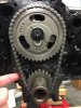
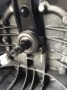
") Since the early gear sets are relieved at the camshaft side a short pin cam might exhibit play at that point.
Since the early gear sets are relieved at the camshaft side a short pin cam might exhibit play at that point.