GTD40 Restoration

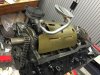
Chaos under the dashboard.
I was checking the horn switch under the dash to see how the switch was connected (+12V supply or earth) by the previous "builder".
Noticed it was setup to switch the +12V however when doing a quick leakage check, it short circuited and also all gauges lights where short circuited to the earth...
Measured the main +12V unswitched (thick brown wire), also short circuited to the earth (30 Ohm and erratic when moving the ignition switch). Luckly I didn't hooked the dash up to the battery :fireman:
Uncoupled the ignition switch and that removed the short circuit of the main +12V unswitched wire but still need to find the real root cause. Going be a needle in a haystack :shifty:

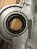
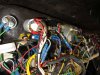
Ignition switch is a Lucas 47SA.
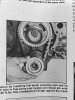
On the photograph you can see the back of the ignition.
On pos 1 ("Starter" should be thin WhiteRed but it is thick Brown)
On pos 2 ("Ignition" should be thick White and is correct)
On pos 3 ("Feed" should thick Brown but is a thin Black)...
aaarghhhh
 

Attachments

  • chaos in dash.jpg
    chaos in dash.jpg
    188.5 KB · Views: 337
Last edited:

Mike Pass

Supporter
Hi Andy,
That looks like a real mess. I guess there are two choices. Check the wiring against the GTD diagrams. I have some better versions with info on late and early colour codes if you need them.
Or bin that loom and get a new one. This may be a better option as the GTD one is a bit light on relays.
Cheers
Mike
 
Hi Mike,
I have all the GTD wiring diagrams (old and new version), thanks.
This looms is an early version however the colors and pins locations at the connectors are messed up (or not according to the drawing).
Indeed, there are not many relays and only a handful fuses, scary.
Currently I am running out of time in order to redo the entire loom.
Want to have the car running in January (and still lot to do like assembly of the engine). This week I gonna pick up the balanced items. For sure I gonna redo the complete wiring loom in a safe way but first need to get on the road for Lemans ;O)

Bit hard to understand how to loom works based on a simple stick diagram with some colors. Some information is missing to understand it properly.
How are the lights of the gauges activated ?
When switching the "dip" switch ?
Is the "light" switch (as called in the GTD diagram) for the "main-beam" ?

I measured 1 ohm between light gauges and earth but that should make sense since all the bulbs make connection and give some resistance...getting too late, bedtime:worried2:
 

Mike Pass

Supporter
I had to replace the fuse box on my car as it had been wired up incorrectly and was too hot to touch and had too few fuses. The thick brown wire and the thin one had been swapped over. I also found that the car had a hidden ballast resistor when it went open circuit on the way to Le Mans! Took me ages to find the problem and ages to put all the wires back in place.
Cheers
Mike
 
Andy,
My ignition switch would have originally been wired up like this:

8681782344_86160961f4_c.jpg


I was concerned it was passing too much current through the switch and so made up this:

13039396695_e6b803f157_c.jpg


The ignition switch now only turns on the relays and allows the power to pass through them.

Regarding the wire size for the starter. It seems large? I have thinner gauge wire that controls a relay for the starter.

Brett
 
Hi Brett,
The wires on your ignition switch are correctly mounted as I interpret the GTD loom. The Lucas Switch 47SA recommends to have only 5 Amps for Ignition and 16 Amps for the Starter so looks you done the right thing, for sure if some high Amperage users are not switched by a relay.

On my other car, I used a push button as a starter hooked to a normal relay hooked to a big Ford solenoid hooked to the starter solenoid, a 4 step switch perhaps bit overdone :O)

Still thinking how to tackle this mess in a short time without buying a new one. Perhaps best to keep the front and rear loom and redo the dash-loom only using most of its existing wires...
lets start with mapping the other looms.

I noticed the "dip" switch has the function for main and dip beam.
What is the purpose of the "light" switch in the GTD loom ?
The small lights below the headlights ?
Which of them trigger the guage lights or are they always on with ignition?
 
About the Light switch and Dip switch in the GTD Loom.

Reading the old wiring diagram this is what I think happens and please correct me if I am wrong.

The light switch is Lucas 31785
  • Brown +12V live on leg 1
  • Red Green on leg 4
  • Blue on leg 8

In Postion 1 (connecting 1 and 4)
Red Green receives +12V which is fused towards Red so all the guages turn on.

In Position 2 (connecting 1 and 4 and 8)
Blue gets +12V aswell which is fused towards Blue Brown which powers the Dip switch

The Dip switch is Lucas 31780
  • BlueBrown on leg 1
  • BlueWhite on leg 8
  • BlueRed on leg 6

Position 1 (connecting 1 and 8) so BlueWhite gets 12V Main Beam
Position 2 (connecting 1 and 6) so BlueRed gets 12V Dip Beam

So found the guage lights :idea: ?
 
Andy,
Attached is what happens with mine on a SGT early loom.

Main Switch - 3 position, forgotten the Lucas number
First position turns on dash lighting and side/rear lights lights
Second position turns on the Dipped

Second Switch - two position
Initial takes feed
Second position switches to Main beam

Hope that helps
Brett
 

Attachments

  • Lights.JPG
    Lights.JPG
    66 KB · Views: 241
Picked up the balanced engine parts. The balance shop told me the new rods are much lighter so that is a bonus and the crankshaft is straight. Flywheel lost quite some some weight as you can see.
Couldn't resist to install the camshaft, crankshaft bearings and crankshaft :drunk:
Endplay in crankshaft is within spec so that is good news.
Upto the next step...
 

Attachments

  • flywheel gebalanceerd 28oz.jpg
    flywheel gebalanceerd 28oz.jpg
    107.6 KB · Views: 293
  • krukas en nokkenas.jpg
    krukas en nokkenas.jpg
    137.1 KB · Views: 259
  • krukas gebalanceerd 28oz.jpg
    krukas gebalanceerd 28oz.jpg
    126.8 KB · Views: 293
  • krukas speling.jpg
    krukas speling.jpg
    104.3 KB · Views: 256
  • new bearings.jpg
    new bearings.jpg
    78.7 KB · Views: 247
Pistons are installed.
Installed the cam gear which came with the engine but noticed it didn't align properly with the top gear and the chain was angled...how could this be ?
Luckly I had still a good set from a 351w double gear which fits and is much better aligned.

In the manual, they talk about the oil slinger...it wasn't installed with the engine. Is this a real necessity ? I dismantled several 302/351w in the past but never saw it been used.
 

Attachments

  • oil slinger.jpg
    oil slinger.jpg
    105.8 KB · Views: 221
  • pistons in.jpg
    pistons in.jpg
    108.5 KB · Views: 252
  • old gear.jpg
    old gear.jpg
    88.7 KB · Views: 219
  • new gear.jpg
    new gear.jpg
    107.8 KB · Views: 222
  • new seal.jpg
    new seal.jpg
    84.3 KB · Views: 240

Randy V

Moderator-Admin
Staff member
Admin
Lifetime Supporter
Andy - Oil slingers are not installed very often anymore. Only a small percentage of the SBF engines made in the last 20 years have them. My advice is to forget it and move on..
 
Andy,
I also went the balance route with my 351 W. I went all internal and had a 0 balance flywheel from Kennedy. Were you determined to stick with the original flywheel? Interesting to see if there are any harmonics in your setup. What is the final weight of the flywheel? I know mine is very light and it revs so quick. There is so much torque in these engines, it probably doesn't matter that much. I am amazed at the smoothness of the engine. There is so little vibration. I have mine hard mounted and have noticed no vibration other than the torque rocking of the whole car at a red light. Have read your thread intermittently. Are you going carb or EFI? You have done some great work on this car.

Bill
 
Hi Randy, thanks for the confirmation. It helps to know I have not to redo a lot of work later on.

Hi Bill, the flywheel was bought new from Southern GT and came in neutral balanced. The previous one was from a ford and they drilled so many holes in the center, considered it as unsafe.
Still Have to weigh the new balanced flywheel. Planned to go internal balanced but I red it was impossible to go from 28oz crank to neutral balanced. This engine is not a high end but hopefully it stays strong for many miles.
The bobweight was 864,5 gram (rotating = 397 and recipro=467,5).
Hope it will be as smooth as you describes.

Currently planning to go with a carburator setup but I still have a proflo from efi on the shelf. Perhaps when I am bored of messing around with the carb
Thanks for the compliments
 
Interesting you say that about the internal balance. The guy I gave the job to gave no indication of a problem. He is a guy with a third grade education who works out of a barn on his property. Sounds like the start of a joke, right?? Name of Charley Peppers. Has every machine and tool known to man about engines. Aluminum or cast. He supplies a lot of the local racers in our section of the country. He is one of those guys that has a feel for what goes on in an internal combustion engine.
When I received my car with the 351 in it, it was supposedly just rebuilt and bored .030 over. Upon arrival I took the oil pan off and it had water in it. Took everything out and sold all. All my racer friends suggested Charlie for the build. Took it to Charlie and he said he could hone the cylinders and get the staining off the cylinder walls. Tried and failed. Suggested to take it to .060 over. I mentioned that I didn't think that was a good idea as I thought it would leave the cylinders walls too thin. He assure me that he did this all the time without any problems. I agreed but told him that if we were going this far to take it to a full rebuild and add a stroker and internal balance to it. He assured me that he could do it and it would be a very stout engine. And that it has. The race car shop that assisted me in the build assembled part of the block components as I wanted the experienced guys doing that part. Had too much tied up in this engine to take a chance on my skills. When we cranked it, it ran terrible. When we talked it over and I mentioned to one of his guys that it was internally balanced, He said it couldn't be, cause the flywheel had been drilled for balance. We contacted Kennedy and they searched their records and discovered they had sent the wrong aluminum flywheel. They swapped it out with no cost to me for a zero balance one. Don't know if it originally was a 28 oz unit to start with, but I do know it is a zero one now. Did they ever make a 351 with other than the 28 oz.?

Bill
 
Can you post the bobweight calculations, there is something seriously phucked up in those numbers... for a SBF the total bobweight per journal should be in the region of 1700/1800 grams...even if I assume your 397gm rotating was one rod big end only the bob weight would only be ~1261.5 gm's....have you got alloy rods?. When I saw the pics of your flywheel a day or two back it looked wrong for 28oz.
BTW neutral balance would have been possible before all this with Mallory metal.
 
Hi Jac,
Perhaps we have to multiply the weight twice.
My balance shop is quite well known in racing in Belgium so I thrust they did a correct job however an error is always possible.
I will make a scan of the balance sheet.
The rods were quite light compared to the OEM onces.
 
Attached you can find the balance sheet.

I think the notes at bottom of page refer to weight comparision between old and new rods.

Attached is balance weight /bob weight calc for a 1970 Boss 302 which wont be far away from what you have... see if you can make sense by weighing your components on a set of electronic kitchen scales.../. it just does not look right to me.
 

Attachments

  • Boss 302 bobweight calc.jpg
    Boss 302 bobweight calc.jpg
    64 KB · Views: 226
Hi Jac,
The bottom shows indeed the weight of both the old and new rods. I also bought some new pins, dont see the weight for this mentioned.
On the bill it give some other details like how much grams are removed.
Flywheel -98 gram
Crankshaft -20 gram
Damper was already 28oz measures 143 gram unbalance. Hope the advertised it correctly and not gave me a 50 oz instead.
Clutchplate -0,9 gram
Pulley 0 gram

Comparing the Boss data, it looks like the ratio between reciprocating and rotating is opposite of eachother. Strange indeed but I gonna proceed. Just realize I swapped the chain gears on the engine which might have an effect on the balance.
Soon I will be able to tell how it runs.
 
Back
Top