
You are using an out of date browser. It may not display this or other websites correctly.
You should upgrade or use an alternative browser.
You should upgrade or use an alternative browser.
GTD40 Restoration
- Thread starter Skorpion
- Start date
Hi Bud, gonna pass by a local accu shop and search through their stock for the proper one. There is for sure one which will fit.
I put the nose back on the car to check for the clearance in case the airco hoses are passing the chassis outside since the radiator is fully blocking the way for a passage from inside. If the hose is halfway up at the front side panel, it will fit and the nose still can flip not rubbing the hose #10. . it is an interesting routing at the inside but should work. To be continued since can start ordering an airco now.
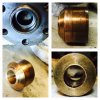
Cleaned the rpm heads and removed all the mud out of it. Looks like it is blastgrid ?
Looks like the previous "builder" used also a kind of transparant household silicone kit not suitable for oils since it just let loose like it never sticked. The harmonic damper was also ready for the trash, the outer ring was not in line anymore with the inner section and looked original from 1969 :laugh:
I put the nose back on the car to check for the clearance in case the airco hoses are passing the chassis outside since the radiator is fully blocking the way for a passage from inside. If the hose is halfway up at the front side panel, it will fit and the nose still can flip not rubbing the hose #10. . it is an interesting routing at the inside but should work. To be continued since can start ordering an airco now.
Cleaned the rpm heads and removed all the mud out of it. Looks like it is blastgrid ?
Looks like the previous "builder" used also a kind of transparant household silicone kit not suitable for oils since it just let loose like it never sticked. The harmonic damper was also ready for the trash, the outer ring was not in line anymore with the inner section and looked original from 1969 :laugh:
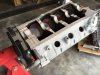
Not so much update on the car itself but more on the engine side.
Trying to salvage the block and checking all its dimensions.
All look within spec so decided to go for its revision.
The long term plan is to put in a 347 stroker but the current block is from 1968 (non-roller block). First it needs running again and see if there are other child-deceases in the build of the car before continuing. Perhaps fuel pumps and other aux...needs updates.
Today I removed the pilot bearing from the crankshaft.
Prepared myself for a battle of a few hours (using the old trick with grease and hammering a tight fit pin in) and it took me only 1 hit and it felt out:stunned:
Looking to the marks, it was only sticking in for 0.2".
That was not good in my opinion :lipsrsealed:
Also decided on the specs of the rebuild.
Since it is a block from 1968, non-roller, stuck with flat tapped hydraulic.
Going for mild, high torque lower HP-rpm cam 218/228@50 (0.471 valve lift). Together with the rpm heads, looking at 340Hp@flywheel and 340 lbfts.
Need to keep the UN1 (not-reinforced) alive.
Attachments
Howard Jones
Supporter
Jac. What about a setup without a heater or bypass hose (used a restrictor instead of a thermostat). Can you just feed the expansion tank from the pump port? I have always wondered about this. Now that I have you on the subject I would like to know the right way.
Last edited:
Jac. What about a setup without a heater or bypass hose (used a restrictor instead of a thermostat). Can you just feed the expansion tank from the pump port? I have always wondered about this. Now that I have you on the subject I would like to know the right way.
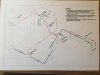
Is this for your GT40/SBF or SLC/SBC Howard, not that it really matters to much ...just gotta remember on either, all fittings on the pump are drawing coolant into the pump, so a hose/line from bottom of expansion tank to pump and a bleed line from top of t/stat housing to top area of expansion tank [but below cap sealing surface]. That bleed line requires a restrictor as mentioned in Andys drawing about 3 to 4mm dia to prevent large volumes of coolant taking the easy route thru the expansion tank. With the 5/8" to 3/4" line from bottom of expansion tank to pump it makes it quite simple to top up coolant level with motor running as it tends to self bleed any air locks, although a complete drain /refill would require a bit more effort to bleed radiators etc. Remember SBC has by-pass drilling in block/heads in front of #2 cylinder, does not seem to worry them that the other bank effectively has no by-pass.
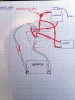
In the drawing you can see both lines of the heater are sucking water on the heater, so no real circulation. I will use the following setup since it works like a champ in my cobra with a stroked 351w.
Even on the hottest days in traffic, the system is stable.
Perhaps it helps.
Even on the hottest days in traffic, the system is stable.
Perhaps it helps.
Attachments
Howard Jones
Supporter
All my bleed lines on both motors/elsewhere are AN-4. Never had a trapped air problem. Both cars are done as you suggest. I have also added a NPT 3/8 drain bung in the lowest water pipe on the car. GT40 in engine room and the SLC is up front in a wheel well pipe.
I thought I was correct but it never hurts to ask "He who is always right". Thanks mate. ummmm................ ya all!!
I thought I was correct but it never hurts to ask "He who is always right". Thanks mate. ummmm................ ya all!!
All my bleed lines on both motors/elsewhere are AN-4. Never had a trapped air problem. Both cars are done as you suggest. I have also added a NPT 3/8 drain bung in the lowest water pipe on the car. GT40 in engine room and the SLC is up front in a wheel well pipe.
I thought I was correct but it never hurts to ask "He who is always right". Thanks mate. ummmm................ ya all!!
Don't think that fella exists Howard!! Doing anything wrong is a very effective means of learning to do it right, but can cost!! I'm still learning something new most days!!! Take today for example, while digging two strainer post hole's for a new fence line I was multi tasking mentally devising a means of drawing up plans for a very accurate mono chassis- no Cad or other fancy stuff, just basic PC 'paint' program plus pencil & paper, and it looks like it will work- wait and see
") . Apologies to Andy for thread drift..
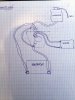
. Apologies to Andy for thread drift..This is interesting! The initial drawing shown is the standard GTD set up and has worked fine on my car for 25 years with just one tweak! I have two pipes from the expansion tank to the same radiator pipe, one from the bottom of the expansion tank and one to the top of the expansion tank. This helps get the air out from the system if I haven't bled it correctly on fill up.
The heater take off connections are the standard FoMoCo water pump positions so not sure why you need to reinvent that bit! Nothing to do with GTD design. Your diagram doesn't show the internal positions of the connections ie which side of the pump they connect to.
Not sure why people remove thermostats as if a correct one is used then it warms your engine up quicker than just a restriction plate and when open is just a restrictor plate in itself! If you get the hole size wrong in your restrictor plate then you can over heat your engine or get impatient and drive your car hard before it is fully warm and knacker it that way.
Malcolm,
If you look at the initial routing drawing "how it was made," both lines on the heater matrix are mounted on top of the waterpump (2 small tubes). Both have negative pressure (suction) so the heater gets no circulation at all, only vacuum :drunk:
Jac's solution or mine shown in the diagram are for sure good solutions. Are you sure your setup is the same as how I draw it initially with regards the heater ? There is currently no hose connected on top of the manifold...but it should be.
I agree with you, a thermostat is important to warm up the engine as quick as possible, especially in Europe. Also the oil needs to get on temperature as quick as possible. I see a lot of oil coolers been placed, make sure the thermostat for the oil is at the right setting (>100 degrees celsius). Otherwise the moist/condensation can not evaporate out of the oil...and reduce lubrication.
Howard Jones
Supporter
I agree that a car that is primarily used as a road car should have a thermostat. I use a restrictor in my car because I had so much difficulty getting the water pump to work at a road race rev range of about 3500-6000 Rpm in very hot weather.
Removing the thermostat and using a thin alum disk with a hole in it seams to have reduced the turbulence in the water supply system just enough to make a difference FOR MY CAR.
The thermostat with all its restrictive workings, is right in the middle of a piece of pipe that not only makes a very tight 90 degree turn but at the entrance is leaving a space larger, than the pipe diameter (intake). Water flow inside the intake is converging from both heads must turn 90 degrees from each side and then meet at the thermostat face where it must flow through the tstat and then make another 90 degree turn to enter the down pipe. Every time water makes a turn it creates turbulence and this spot is just about the worst one on the car.
On top of that the pump is trying to live with a impeller speed range that is frankly beyond its limits and the whole thing is one huge compromise.
Again this is what I need to do to get my car to run 30 mins at engine speeds never seen on the street for that length of time and have the water temp remain stable at about 190F. To add to the problem we can't run water system additives, just plain water, and the air temps are routinely above 103-105F.
Then there is track surface temps that can easily reach 150F. The radiator inlet duct is 6 inches above that.
My car needs all the help it can get. Thus no thermostat.
Howard Jones
Supporter
Andy. In my case running the pump too fast is the problem. I made my own water pump pulley just so I could slow it down. Mechanical water pump impellers will all experience cavitation at about 4000RPM (pump speed)or less. The idea is to keep the pump flowing enough water when the engine is at low speed and at the same time not over rev the impeller when the engine is at its rev limit under full power.
This IS the reason for electrical pumps that run at a constant speed or run within a narrow speed band depending on cooling needs. Here's some info on Cavitation. As you can see a mid engine car is just about the worst case example for a water pump. see question #2
Q&A: Pump Cavitation Diagnosis & Control | Flow Control Network
Here's some more stuff;
Cavitation - an Introduction
Cavitation
What is Pump Cavitation?
Water pump cavitation solution • Speed Talk
Last edited:
TBH you can remove the heater matrix from a GTD as the car always seems to get warm without the need for extra heating! That big windscreen is great for solar energy capture! And if you track the car you will gain performance from the weight loss. When I have used the heater it seemed to work but just not like my everyday car heaters.
Hi Jones,
I did worked for the oil pump industry :laugh:
Passed my examen for theoretical design of pumps many years ago epper:
Indeed higher speeds will cause cavity but it is depending on the impeller design, fluid and pressure. The impeller design on our waterpumps is very basic - at least from the pumps which I opened so far. With regards pressure, I am not so convinced there is a lot of pressure but fore sure the design of the impellers is asking for troubles. Sometimes just straight vanes. They should be curved in all directions...in best case they are curved vanes only in 1 plane.
Cavitation is a strange effect, a kind of micro burst possible to destroy your impellers. We had some test setups to show people and it can destroy huge blades. Witnessed big oil pumps (2 feet impellers) running at max speed with the outlet tube shut so worst case situation...the total building was shaking :stunned: and impellers 2" thick could bend. Crazy stuff.
Anyway, a CVT (Continuously Variable Transmission) design on the pulleys would be great for you :idea:
CVT how it works
The idea is simple but to make it work requires some additional work.
An electric pump sounds best in your case.
You are running a high compression engine dissipating quite a lot of heat ?
Myself, I am planning to not hook up the heater matrix...it will be present part of the airco unit but not connected.
I did worked for the oil pump industry :laugh:
Passed my examen for theoretical design of pumps many years ago
epper:Indeed higher speeds will cause cavity but it is depending on the impeller design, fluid and pressure. The impeller design on our waterpumps is very basic - at least from the pumps which I opened so far. With regards pressure, I am not so convinced there is a lot of pressure but fore sure the design of the impellers is asking for troubles. Sometimes just straight vanes. They should be curved in all directions...in best case they are curved vanes only in 1 plane.
Cavitation is a strange effect, a kind of micro burst possible to destroy your impellers. We had some test setups to show people and it can destroy huge blades. Witnessed big oil pumps (2 feet impellers) running at max speed with the outlet tube shut so worst case situation...the total building was shaking :stunned: and impellers 2" thick could bend. Crazy stuff.
Anyway, a CVT (Continuously Variable Transmission) design on the pulleys would be great for you :idea:
CVT how it works
The idea is simple but to make it work requires some additional work.
An electric pump sounds best in your case.
You are running a high compression engine dissipating quite a lot of heat ?
Myself, I am planning to not hook up the heater matrix...it will be present part of the airco unit but not connected.
Similar threads
- Replies
- 4
- Views
- 1K
- Replies
- 11
- Views
- 1K