GTD40 Restoration

Dismantled the front bearing to check and everything felt hand tight so I dismantled it completely to check.
I do not thrust anything anymore with the previous builder.

I have some questions related to the front wheel hub
a) is the conical bearing SKF EK-LM1149 the right one ? used in Ford Escort MkI
b) how much torque does the nut need ?
c) is that ring with notch okay, it looks to me wrong and bend.
 

Attachments

  • lagers.JPG
    lagers.JPG
    136.5 KB · Views: 328
Last edited:
Those are MK2 Granada front hubs - the bearings should obviously be for that unless your uprights are off something else? As far as I know the Escorts all had 4 bolt wheels.
 
The uprights are shown on the pictures.

I removed all paint between the contact surfaces...

Measured the bearings, looks like indeed for a MK2 Granada.
Outer bearing OD 50mm, ID 29mm, width 14.5mm.
Inner bearing OD 40mm, ID 17.5mm, width 14.5mm.
 

Attachments

  • uprights.jpg
    uprights.jpg
    122.2 KB · Views: 418
  • uprights2.jpg
    uprights2.jpg
    136.1 KB · Views: 439
Last edited:

Mike Pass

Supporter
GTD front uprights and hubs are usually Mk2 Granada which are 5 stud. I will check tomorrow for the bearing numbers and tightening procedure.
Cheers
Mike
 

Mike Pass

Supporter
Ford Granada Mk2 front wheel bearings available here:-

Granada Mk2 - classicpartsshack

or here

Wheel bearing kit (front): Ford Capri 3.0 10/71-, Granada Mk1/Mk2; (rear): Escort Mk3/Mk4 (not Van)

Tightening procedure and torque settings attached. There needs to be a small amount of running clearance in the bearings to allow for expansion when hot due to running and braking.

I set them by tightening with a short spanner whilst spinning the wheel to settle the bearings into running position and then slacken the nut off slightly so that the clearance can just be noticed at the wheel rim by rocking the wheel. The hand tightness on the main nut you noticed when dismantling the hubs is probably about right. Always use a new split pin to secure the nut.

Cheers
Mike
 

Attachments

  • Granada Mk2 front torques.jpg
    Granada Mk2 front torques.jpg
    432.1 KB · Views: 257
  • Mk2 Granada front hub adjust.jpg
    Mk2 Granada front hub adjust.jpg
    401.8 KB · Views: 265
Hi Mike,
Thanks for this valuable information.
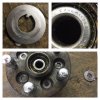
There was no rock in the bearings and they were quite freely so it looks like it was done correctly.
I need to re-mill one side of the brake disc since it was attacked by a guy with a grinder :shout:

Tested the radiator (orginal GTD40) and unfortunately it is leak...water was pooring harder out as in :stunned:
Need to score an affordable radiator on the short term to make LeMans in time :drunk:

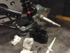
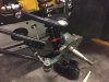
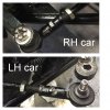
Today, I studied the steering rack position and did a rought alignment of the front wheels. While the steering rack position was in the middle (counted the turns on the steering wheel and determined the middle of the travel)...
Noticed I couldn't get the left wheel straight while the right wheel was straight.
It looked like the balljoint on the rack where not evenly positioned towards the chassis in the middle position and the left end of the steering rack was shortened (again that grinder...)
Normally there is 50 mm thread on, only 36 mm was on the left steering rack end.
Situation was that the tie rod was not even touching the thread on the steering rack end.... what was going on ???
While removing the gaiters of the steering rack, the left gaiter was full of loose tie-wraps ??? WTF ? what a lazy previous builder..."whatever" I was thinking, didn't surprised me anymore.
Okay, I just removed them and start remeasuring again and investigating why the steering rack was not centered to the chassis since I measured a deviation of 20 mm ....Noticed, I couldn't move the steering rack without rewelding the mounts....mhhhhh....scratching the head. Don't want to go that direction.
Then, I turned again the steering wheel to find the middle of the steering position and suddenly the steering wheel could turn 3.75 times. This is more as earlier while I could do only 2.25 times....WTF :idea:
The tie-wraps in the left hose were blocking the travel of the steering rack !:shout:
Okay, I rechecked the middle position and found the steering rack position is spot on !
Since the left side is cut, only 3 threads of steering rack end goes now into the tie rods for a straight wheel position so not enough to my opinion...
I have now 2 options, going for an extensioner but that looks crap.
I will go for another steering rack Cortina Mk3.
Too make a long story short...what some tiewrap left in a rubber gaiters can do....
 

Attachments

  • ends LH car not possible.jpg
    ends LH car not possible.jpg
    129.4 KB · Views: 312
Hi Mike,
Thanks for the links. Internet is a great place to source stuff.
How the world changed over the last 10 years with internet trading/webshops is unbelieveable :thumbsup:
Regards
Andy
 
Hi Mike,


Tested the radiator (orginal GTD40) and unfortunately it is leak...water was pooring harder out as in :stunned:
Need to score an affordable radiator on the short term to make LeMans in time :drunk:


Andy,
I have a used but perfectly OK and sound GTD radiator that you can have FREE if you wish. I don,t know what it would cost to post to you though.
 
Last edited:

Brian Magee

Supporter
Andy,

The tie-wraps were most probably there as a crude way to stop the tyres touching the chassis on full lock. Check the lock with the wheels on before you finish with the rack, you may need to fit some internal stops.

Brian.
 
Hi Graham,
thanks for the offer and I like to take use of your offer ;-)
Sent you a PM.

Brian,
That might be indeed a good reason but the tiewraps were loose and dangling just in space without being wrapped around the rack. But good thinking. I will check this aspect.

Thanks for the support guys !
My aim is to join Lemans Classic with the GTD40 !
 
On the GTD40, the "original" torsion bar gave some room for the battery. The new torsion bars are straight so limiting a bit of the height if you want to but the battery against the rear wall of the front compartment.
Most batteries are 195 mm heigh but I needed to stay below 180 mm.
Found 2 battery who suited for the job...
VARTA D21 or Bosh S5004.
To my research, they both are made in the same factory.
Dimensions
height 175 mm & Length: 242 mm & Width: 175 mm
Voltage: 12 Volt & Capacity: 61 Ah & Startercapacity: 600 amp
Type: Calcium
My experience with Varta is so far good, the one in my cobra does still its job perfectly after 10 years, still able to provide juice for the starter which needs to push against some high compression. Not even hooking up the battery to any battery saver device.

It is a nice fit and happy with it.
Next up the action list is making a stainless battery tray fixed to the chassis instead of screwing it into the glassfibre sheet only :shocked:

Expecting a lot of parts to come in during the coming weeks so I can finish of the suspension and start on the engine rebuild.
First idea was to have only the new neutral balanced flywheel re-balanced to 28 oz however this is not possible without the other parts or a referenced flywheel. Guess it is better after all to balance all rotating and moving parts so I hopefully end up with a smooth and silk engine.
 

Attachments

  • accu.jpg
    accu.jpg
    119.9 KB · Views: 285

Keith

Moderator
Hi Andy, by 'torsion bar' do you mean anti-roll bar?

I only ask in case you have a different kind of front suspension!
 
Yes, sorry, I keep mixing up the terminology...torsion bar and anti-roll bar....
My previous project was a 911 from 84, which had torsion bars and anti-roll bars :pleased:.
 
Today focussed on the pedal box and setting it up making ready for final mounting.

The front brakes are Wilwood 6 pots, the rear standard GTD40 Granada I think.
The following master cylinders were used on the car.
The master cylinder bore for the front brakes is 0.625"
The master cylinder bore for the rear brakes is 0.7"
(The master cylinder bore for the clutch is 0.75")
Brake Pedal ratio is 6

Measured the maximum stroke on the mastercylinders when pushing the pedal to the metal and turned out to be 1.1"stroke (80% of the max stroke of the master cylinder). Would like to go for the 90% but in that case the pedal-ends starts to lift quite high and pointing too much forwards...

I used a calculation sheet from internet which says the brake power is 75% at the front and the rear brake line is at its maximum psi level. Probably testing in real life is better but would like to estimate if I am already in the ballpark and using the right bores.

Does anyone has experience with this setup - 6 pot wilwood and bore sizes ?
 
A quick repeat to get this post higher in the ranking :laugh:
Does anyone has experience on the GTD40 with at the front; 6 pot wilwoods and the rear the standard GTD40 brakes ?

Knowing your bore sizes with this setup helps to get an indication if the current setup is in the ball park. Trying to achieve first time right principle, I mean, trying :thumbsup:
 

Howard Jones

Supporter
Here's a known really good baseline to work from. My GTD has 4 pot 1.75 diameter piston front superlight Wilwoods and 1.38 piston 4 pot superlight Wilwoods on the rear. Same 12 X 1.25" wildwood HD rotors both front and back.

I still have the original tandem Granada master. Both front and back are 5/8" I believe. Can some one confirm this for us? I also have a adjustable proportioning valve in the rear brakes. I believe it is set to reduce rear bake pressure about 10%.

These brakes I have work so well that just don't get out braked during a track day event.

Feed in my system to the calculator below and then use it as a baseline for your proposed set up. You will need to know the piston sizes of every thing. I used 6 to 1 as a peddle ratio. My car has the GTD power brakes setup and the combined result is pretty near 6 to 1. You will need to best guess some of the variables but as long as you keep them constant you can still get some good comparisons. Concentrate on torque values and their bias relationships front to rear. Use my values as a guide.

For pad frictions use Wilwoods steet/traceday combo pad. Look it up on their webpage or use .5 as a value. That is pretty close and as long as you use it for both mine and yours you will be fine.

Use 2500 pounds with 1100 F 1400 R for both cars again. Every thing else on our cars is fundamentally the same. I run street tires on my car.


Dual Bias Calc.
 
Last edited:
Back
Top