Howard B's RCR 40

Howard,
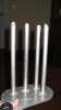
You can use several designs. They are just designed to keep the big particles that get into your tank, out of the system. You still have to use a good filter before you get to your pumps, preferably one with replaceable filters. These types will help with water extraction as well. Some station owners will let their tanks go down to just about empty especially when prices start to rise, or we run into a shortage ala Jimmy C. A lot of fuel filters start to clog around that time due to the crap getting sucked up. You have to do some routine maintenance to keep the system running freely as Dimi pointed out. Here are some other sources of the fuel "socks"
Pegasus - Keyword Search
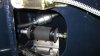
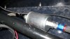
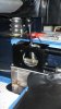
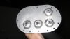
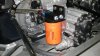
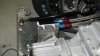
These are the type I put in mine My tank attachment was on the end of the tank, so it bends around at the first baffle and stays flat on the floor.
Fuel Pick-up Kit - Fuel Safe Fuel Pick-up Kit 1/2" - 8 AN

You might want to consider a surge tank in the tank itself to keep fuel pickup of air when you park downhill or hit the brakes rather vigorously on a low tank. A simple trap door on the rear baffle works well.
Fuel Safe Racing Fuel Cell Surge Tank Trap Doors and Check Valves

Bill
 
Time to crawl out from under the log and post.

I am getting close to a first start. I have been chipping away and getting stuff squared away on the car.

The Dynatek Classic EFI set up, which was designed for front engine cars had a lot of extra wire, so I ordered some connector ends and re-sized all the wires so I won't have miles of spaghetti under the back clip.

I figured out hiding places for the high pressure fuel pump and filters inside the chassis on the passenger side. It's going to all be hidden and still be accessible. See the pics.

I built a little frame so the fuel lines won't be chafing on the internal bulk heads.
 

Attachments

  • Fuel Pump Filter 0ne 044.jpg
    Fuel Pump Filter 0ne 044.jpg
    28.8 KB · Views: 422
  • Fuel Filter two 046.jpg
    Fuel Filter two 046.jpg
    34.6 KB · Views: 398
Oh yeah,

I had John at Design Enterprises put a shifter mount together for me and now I actually have more fun sitting in my car going vrooom vroom! :laugh::laugh:

I hooked up the pedal assembly and strung the accelerator cable from Lokar.
It required some bracket fabrication which I made out of extra garage door parts I had laying out in the other garage.

Wiring of the Isis wiring harness is almost complete with a few things to be completed such as the signal wires to the gauges.

A couple of more pics...
 

Attachments

  • Shifter picture 2 006.jpg
    Shifter picture 2 006.jpg
    20.9 KB · Views: 504
  • Dash pedals 016.jpg
    Dash pedals 016.jpg
    42.7 KB · Views: 660
Oh Yeah,

I forgot to thank my friend Bill for getting the clutch stop welded onto my pedal assembly.

Thanks Bill!

Here's a couple of pics for me to feel good about I just set the body panels on to give me the appearance of nearing completion. LOL
 

Attachments

  • Front view 031.jpg
    Front view 031.jpg
    29.6 KB · Views: 455
  • Side view 035.jpg
    Side view 035.jpg
    31.3 KB · Views: 566
Impressive progress Howard
I noticed the steering coloum sits quite high is it a RCR part or out of another vehicle? If you dont mind measuring, Where the steering wheel sits how high is it off the floor.
How do you get on with right hand drive , do you drive it on the street
Woody
 
Woody,

Sorry to be slow to respond, I haven't checked in to the site for a while.

Yes, it is an RCR steering column. The height from the floor is 18.5 inches to the center of the column. However please note it has been trimmed and is adjustable in and out, which changes the height from the floor. Mine will be a little further out, and thus slightly higher from the floor. It has been designed to collapse in an emergency. It fits quite snugly under the dash.

I do plan on driving it on the street, right is right and left is wrong on a GT40. :thumbsup: I am certain it will be a little challenging when I get it up and running.

Cheers,
Howard
 
One step forward, two steps back.

John at Design Enterprizes sent over my swirl pot bulkhead plate with welded AN fittings and fuel tubes attached for the EFI system.

I promptly went to work drilling mounting holes in my swirl pot tank and shortening the tubes to the proper lengths. I filed down the burrs on the tubes and proceeded to drop the plate on the floor crushing the aluminum AN fittings on the top. :shocked:

Well, I boxed it back up and sent them to John, and told him they arrived broken. :laugh::laugh:. I actually fell on my sword and told him what had happened. :thumbsup: He will help me straighten out the damage. They have done a really nice job, only to have a fumble fingers customer bung up the job.
 

Attachments

  • Fuel Plate Top 005.jpg
    Fuel Plate Top 005.jpg
    22.3 KB · Views: 375
  • Fuel Tubes 013.jpg
    Fuel Tubes 013.jpg
    13.3 KB · Views: 1,410
Needing a sense of accomplishment this week I mounted the remote oil filter unit. I made a mounting plate and attached the unit to the back left side of the trans-axle.
 

Attachments

  • Oil Filter 008.jpg
    Oil Filter 008.jpg
    41.2 KB · Views: 501
  • Oil Filter Back 007.jpg
    Oil Filter Back 007.jpg
    33.1 KB · Views: 439
Thanks Woody,

Have a Speights, good on ya' mate! :laugh:

My son and daughter-in-law are residents of Dunedin. Where are you located in Kiwi land?

Cheers,
Howard
 

Chris Kouba

Supporter
Howard,

I assume one of these pipes is an outlet for the return line back to the sponsons, right?

attachment.php


If so, you may want to trim the appropriate tube so that it's at the top of the swirl tank. This would allow it to expell the air from tank and it will also determine the "full level" of the swirl tank.

Give me a call if you have some time to kill at work- anytime after 11a eastern should be fine (I'm supposed to be up early).
 
HOward,
I am with Chris on this one. The line that will be your vent/rollover has to be short(maybe not has to be but it seems like it to me) at the top in order to let the air out. I am assuming two things here. Your swirl pot as it is, has an opening near the top into the rest of the tank so that when it is full it will spill over to the rest of the tank. And two you have a trap door at the bottom to let fuel in when the level in the swirl tank drops below the level of the rest of the tank.Speaking of which, I am assuming you have restrictions in the tank that will keep it from sloshing? You may have addressed this earlier and I just missed it.

Bill
 
Chris and Bill,

Nope, no extra pipes and trap doors. The design idea is taken from Dean Lampe. The overflow will be a hole cut in the top of the bulkhead between the two tanks (left tank and swirl pot). The air should also escape through the same hole back into the left tank where there is a tip over valve. No extra hoses needed on this arrangement. Fewer parts fewer problems. He says with his fingers crossed. LOL
 
Hi Howard
I'm about 1 hour south of the largest city, Auckland in a rural town of Pukekohe in the north Island But we are not Aucklanders. Ask your son or any other southerner, they call those folk Dorklanders:laugh:
How ever we do enjoy the southern drink of Speights, you got that right.
I got fond of drinking Millers and Corona in the US. I stayed a bit in North Carolina Ventured up to Richmond VA to watch Nascar, Thats bout as close as I've been to your neck of the woods Surely is a beautiful place in the world.
Keep up the good work
Woody
 
when this happens the coolant doesnt remain in the engine long enough to efficiently absorb heat and carrt it away to the radiator

not sure what you mean here, can you emphasize? the cooler the water the higher the temperature difference the higher the heat flux, hence better cooling for lower water temperatures.

The lower the flow rate the more (energy) efficient the system is - since not much friction is created in those pipes (lower flow velocities, lower friction, more energy efficiency).

If you want maximum cooling and if you don't care about energy efficiency (implying that the system might need several horsepower), then you set the pump at maximum flow rate at idle. The higher the rpm at the water pump, the higher the (input) pressure (even if the water pump cavitates, but then the increase is nonlinear and super inefficient), the higher the flow rate. Higher flow rate means higher possible heat flux. A higher flow rate causes (a little) more turbulence, increasing the ability to take away heat from the hot walls since heat transfer is of convective nature (that is, heat conduction enhanced by fluid motion).

Maybe what you are referring to is that if the system pumps too much water, the cooling will be "too much" and hence the engine can't reach its operating temperture.
 
Well let there be light! :stunned:
The Isis wiring harness is good stuff...

The fourth picture is the Boss 302 hanging (the business end) out the garage door... :veryangry:

and the 5th picture I call "siblings"... :pleased:
 

Attachments

  • Light 1.jpg
    Light 1.jpg
    107.3 KB · Views: 401
  • Light 2.jpg
    Light 2.jpg
    102.8 KB · Views: 375
  • Light 3.jpg
    Light 3.jpg
    106.8 KB · Views: 396
  • The business End.jpg
    The business End.jpg
    125.3 KB · Views: 494
  • Siblings 1 11711B.jpg
    Siblings 1 11711B.jpg
    110.4 KB · Views: 427
Great work! Looks sharp. It took me about a day to go through all these posts to catch up on what Ive been missing, plus popcorn runs might have been the other cause that it took so long to read, but then again it was a great read! I took a tour through RCR a few months ago, They do a great job and you have a great car. Cant wait to see it all done and on the road
 
Back
Top