Installation of Jenveys with Emerald ECU on my 302

Terry Oxandale

Skinny Man
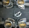
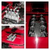
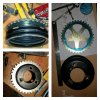
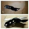
Installed throttle linkage.
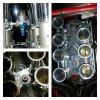
Jenveys have very little clearance between the throttle body flange and the lever. Plus there is overlap of the manifold flange. Easily fixed by taking off 1mm off the manifold flange and grinding down the ball joint bolts to leave clearance between nyloc nuts and the flanges.
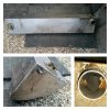
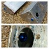
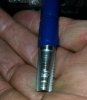
For the pivot I welded a boss onto a 5/16 unc bolthead drilled and tapped it 5mm x .8 to take the pivot bolt. Goes in the central stub on the Cobra manifold.

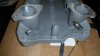
Curious about the difference in angles of the two pushrods coming off the bellcrank to each bank of TBs (not symmetrical). Is this a photo distortion or without everything in the proper place?
 
Last edited:

Dave Bilyk

Dave Bilyk
Supporter
Hi Terry, Thanks for the heads up, it's not a photo distortion. The centre boss in the manifold is about in line with one of the ball joints so that is where it naturally sits. I will have a look at how I would realign it.
 

Attachments

  • 2017-04-30 19.13.28.jpg
    2017-04-30 19.13.28.jpg
    131.1 KB · Views: 415

Terry Oxandale

Skinny Man
I was going the other way on that (lengthening them) to get as much of a progressive action as is possible with that bellcrank (if I'm not misunderstanding you). My set-up, which has avoided all the issues of throttle response commonly voiced in various forums with ITBs, has the initial motion of the bellcrank connector nearly perpendicular to the centerline of the links themselves. So the initial push on the throttle nets little plate movement, but also results in very quick opening once the throttle is already well open on the last third of WOT. This does require more pedal motion, but provides excellent modulation of the throttle.

Poor photo, but this perhaps illustrates what I finally came up with on the geometry (it's homemade, so please forgive the utilitarian appearance:

standard.jpg
 
Last edited:

Dave Bilyk

Dave Bilyk
Supporter
Thanks for the input guys, I will check this out further down the line.
On to the fuel tanks which need a return line connection. I took the RH tank out, having marked the available area for a connection on the rear facing end of the tank. It would save a lot of effort if I could drill and fit a bulkhead connector, not sure if that is a reasonable way to go about it but with the proper fitting worth considering if it avoids a complete degas for welding.
When I looked at the foam in the filler neck the reason for my oh so slow filling became clear. It would have been better if a small compartment had been left foam free so that a greater area of foam was presented to absorb the fuel more quickly.
There is one baffle at the rear to create a compartment for the level sender and the pickup.
Do I pull all the foam out and replace it with explosafe or foam beads or chunks?
Dave
 

Attachments

  • Fotor_14938425192629.jpg
    Fotor_14938425192629.jpg
    155.2 KB · Views: 387
Last edited:

Ian Anderson

Lifetime Supporter
Broomstick through the filler hole to push a hole into the foam?

On the fuel gauge sensor
Can you remove said part? If so is there enough space thereon to drill and add the return?.

This can then be removed and drilled and welded away from the tank, fumes etc.

Ian
 

Dave Bilyk

Dave Bilyk
Supporter
Ian, good ideas, thinking out of the tank eh!
I will remove some foam from the filler area and maybe put a mesh tube in there to keep it free.
The sensor already has a vent connection so I could re-purpose that and make a vent connection somewhere else, but it looks tight on the sensor for an additional connection. I'll be comfortable drilling a hole in the end of the tank and just need to find the right fitting.
Dave
 

Attachments

  • 20170503_204508[1].jpg
    20170503_204508[1].jpg
    303.7 KB · Views: 354

Ian Anderson

Lifetime Supporter
Dave

My Tanks are different to yours too.
Filled with explosafe (wire wool) stuff

Up at front there is a breather next to filler hole that is vented up to immediately under the filler cap!

But as you have found mine did not have returns, but they were added prior to the tanks ever having had fuel added.

Strange how 2 Dax have such different tanks.

Ian
 

Dave Bilyk

Dave Bilyk
Supporter
Ian, I guess there will be other differences too if we compared.
Interesting that you have a vent at the front, my fuel sender is trapped in a space between chassis rails, so the builders had dented one edge of the tank to get the pipe out. The pipe then runs forward below the tank, and up to the vent outlet as in yours below the filler cap. Now here's the funny bit; because the pipe beneath the tank tends to collect fuel, so when I start to refill, a fountain of fuel comes out of the vent as the collected fuel is displaced. That and the slow filling makes it a trial. Anyway, now I have the opportunity to fix it! Maybe I will reroute vent outlet to the back but I'm nervous about rerouting a vent into the engine compartment.

I think that the vent connection on the fuel sender is the right place because it's in a foam free compartment and at the opposite end to the filler, I can't get an additional connection for the return in there, so I will drill a hole at the back of the tank. Still trying to find a UK tank stub / bulkhead connector - (plenty on US sites and I note Moroso has a tee for the fill pipe, but I don't want it to go all the way to the front.)
Dave
 

Dave Bilyk

Dave Bilyk
Supporter
Trial fit of 48 x 120mm trumpets. There's about 2.5" clearance to the window.
 

Attachments

  • Fotor_14950483456831.jpg
    Fotor_14950483456831.jpg
    135.4 KB · Views: 414

Dave Bilyk

Dave Bilyk
Supporter
Thanks guys, I'm way below the expertise shown by many of you on this site, and I value all your advice and comments. Next tasks are to mount the toothed wheel on the pulley, and place the pump and filters, ecu and sensors etc.
Dave
 

Dave Bilyk

Dave Bilyk
Supporter
This weekends efforts. Made a bracket for fuel pressure regulator. Fits neatly between trumpets with plenty of space below for the outlet pipe.
Removed LH fuel tank and removed the rear vent pipes, and cut them short to reroute them to the front.
I was also looking for a silicone y pipe for the twin outlets on my cobra msnifold but no joy yet, is there such a pipe or must I fabricate something?

Dave
 

Attachments

  • Fotor_149537531160665.jpg
    Fotor_149537531160665.jpg
    145.4 KB · Views: 419

Dave Bilyk

Dave Bilyk
Supporter
Tonight I cut the centre of the toothed wheel out, using my best apprentice skills to file it to my marking out until it tapped onto the pulley. The id of the outer ring just happens to be the same as the pulley hub od which helped. Next I will finalise position, weld then true up the teeth if necessary.
Dave
 

Attachments

  • Fotor_149548829722464.jpg
    Fotor_149548829722464.jpg
    142.7 KB · Views: 375

Dave Bilyk

Dave Bilyk
Supporter
Return connectors installed in tanks. Easily accessible through the level sender hole.
Dave
 

Attachments

  • Fotor_149590070710921.jpg
    Fotor_149590070710921.jpg
    151.5 KB · Views: 356

Dave Bilyk

Dave Bilyk
Supporter
Today I installed the rear air bleed connections in the intake manifold. It didn't quite go according to plan, but I think that it was ok in the end.
The last time I did this, I had a little bit of difficulty with the 1/8 - 27 NPT taper, finding it much more difficult by hand to keep the tap square on as it tended to wander and enlarge the thread a little. This time I had that nailed, as I used a fitting around the tap to make sure it was square on and went slowly, checking all the time. The job was a good un, for both holes, however, on the second hole, I didn't back the tap up for the last 1.5 to two turns, and although it felt fine going in, it locked solid as I tried to back it up. The result you can see in the picture, aluminium welded in the tap threads.
The fitting only went in half way, so there was at least some metal left, I cleaned the tap and re-threaded, and tried the fitting, giving it a good heave to make sure it was strong enough then backed it out and refitted with a dose of chemical metal to make sure. A bit of a bodge but I believe I got away with it:lipsrsealed:
Dave
 

Attachments

  • 2017-05-28 16.51.38.jpg
    2017-05-28 16.51.38.jpg
    166.8 KB · Views: 367
  • 2017-05-28 17.51.31.jpg
    2017-05-28 17.51.31.jpg
    316.7 KB · Views: 359

Dave Bilyk

Dave Bilyk
Supporter
Bracket for Toothed Wheel Sensor. Since I found it impossible to measure, this was a trial and error exercise. A few stiffeners welded on to avoid vibration / contact of the sensor tip.
Dave
 

Attachments

  • Fotor_149599243548056.jpg
    Fotor_149599243548056.jpg
    101.1 KB · Views: 357

Kevin Box

Supporter
Dave

Good to see progress being made

I'm keen to see what you do with the two water outlets and thermistat


regards Kevin B

:thumbsup:
 

Dave Bilyk

Dave Bilyk
Supporter
Hi Kev, I'm on a mission to get this done by August:)
Ok, so I have a Davies Craig Electric Pump, so thermostat is out.
You can catch up on that saga here Water Pump

So the two water outlets just need to connect directly to the main return pipe.
Dave
 
Back
Top