Joel’s SL-C Build Thread

Nice, ambitious! Are you planning to baffle the interior of the tank so you don’t run into issues with pump starvation in turns with low fuel level? I believe in other in-tank conversions I’ve seen most people have added some type of internal baffling to help with that. Without running a swirl pot there won’t be much fuel volume to back you up if there’s a pickup issue.

Going with an in-tank will help with the noise, I can hear my external pumps working away when the car is running. It’s not intrusive, but you definitely know the pumps are running. Maybe some kind of shielding to help block the noise would help but I imagine the in-tank route is going to be dead quiet.

Is it just a weird angle, or is the floor of your fuel tank compartment not fully closed out? Looks like there’s only about a 3-4” plate forming the bottom of that area.
 

Joel K

Supporter
Nice, ambitious! Are you planning to baffle the interior of the tank so you don’t run into issues with pump starvation in turns with low fuel level? I believe in other in-tank conversions I’ve seen most people have added some type of internal baffling to help with that. Without running a swirl pot there won’t be much fuel volume to back you up if there’s a pickup issue.

Going with an in-tank will help with the noise, I can hear my external pumps working away when the car is running. It’s not intrusive, but you definitely know the pumps are running. Maybe some kind of shielding to help block the noise would help but I imagine the in-tank route is going to be dead quiet.

Is it just a weird angle, or is the floor of your fuel tank compartment not fully closed out? Looks like there’s only about a 3-4” plate forming the bottom of that area.

Hi Cam, right now don’t think I will need to baffle the tank. The stock fuel pump has a jet pump which fills up the fuel bucket so it works similar to a swirl tank.

Another option would be to add two fuel pick ups in series, one next to the fuel pump and another on the far end. These look pretty clever....

http://autoperformanceengineering.com/html/pickups.html
 

Joel K

Supporter
Nice, ambitious! Are you planning to baffle the interior of the tank so you don’t run into issues with pump starvation in turns with low fuel level? I believe in other in-tank conversions I’ve seen most people have added some type of internal baffling to help with that. Without running a swirl pot there won’t be much fuel volume to back you up if there’s a pickup issue.

Going with an in-tank will help with the noise, I can hear my external pumps working away when the car is running. It’s not intrusive, but you definitely know the pumps are running. Maybe some kind of shielding to help block the noise would help but I imagine the in-tank route is going to be dead quiet.

Is it just a weird angle, or is the floor of your fuel tank compartment not fully closed out? Looks like there’s only about a 3-4” plate forming the bottom of that area.

Cam,

With regard to the weird angle, good catch. The fuel compartment is half closed/covered. I have the extended foot box and they chose to cut the whole chassis pan including the front foot box out of a single sheet which shortens the length of the pan near the fuel tank area. I really don’t like the way it was done, but it is what it is. I’ll get a 6” x 72” sheet and close it out. Maybe have it welded in or rivnut it so I can remove it for some reason.
 

Joel K

Supporter
Ken, I have not looked in the tank but will take a peak through the sender opening.

Just checked, yes I can see two baffles , one on each side of the sender so this should work without worrying about fuel starvation.

Thanks for the heads up.
 

Joel K

Supporter
Spent some time on the build yesterday and made the modifications on the fuel tank required for the stock Camaro ZL1 pump as well as adding the roll over-vent valves.

Parts used
1)Gen5 Camaro ZL1 fuel pump
2)Weld in aluminum fuel pump ring from VaporWorx.com
3)Rollover valve weld in bung from boydwelding.com
4)Rollover-vent vale’s from fordpartsgiant.com, Part No.: F65Z-9B593-DA VALVE ASY - FUEL VAPOUR
5)1/8” sheet aluminum from McMaster Carr

I marked off where I wanted to cut the tank with masking tape, it makes it easier to follow along when cutting. The pump is spring loaded and can be mounted 6-7” from the bottom of the tank with a recommended depth of 6.5”. You also need to cut enough of the tank away so there is enough room for the weld in ring which is 7” wide. It turned out 6.5” from the bottom give you over 8 inches of flat surface on the top so that is where I marked the cutting line.

Also, based on the surface area cut away I will lose around 1.5 gallons of fuel tank capacity which I don’t think is a big deal.

Here is a video of the plan...

Pics of the tank prior to cutting...
CA5FFAF6-BFD9-403B-AF53-490917A28E38.jpeg


CA5FFAF6-BFD9-403B-AF53-490917A28E38.jpeg

CDFFB85A-0A32-49A0-B54F-6659F5135F6F.jpeg


After cutting the tank the pump hat is about an inch from the top of the tank, then the hat springs compress to keep the bottom of the fuel pump pressed to the bottom of the tank.
62F8EB0F-532E-422E-AFE2-79EEA085FC13.jpeg

0AD481F6-771A-4B93-B9AE-C5C946AAE5F9.jpeg


Cut a 6 3/8” hole for the fuel pump ring....
2BE53B69-CE57-4287-9892-289047D51D67.jpeg


The tank is now ready for the welder including the roll-over valves...
313FE940-894D-4041-BB31-D301D86D2BB4.jpeg


Video of the tank modification ..
 
Last edited:

Joel K

Supporter
A little progress on the build.

Modified engine shipping crate and made it into an engine stand...

Lifted the engine from the crate...
956B9F08-B32A-447B-A2EE-1AAEEA4FF094.jpeg


Modified it so I could mount accessories and have clearance for trans adapter plate. Also added wheels.
F9FB61E1-E9C2-4077-BF3F-B57BD731CD6E.jpeg


Attached the flywheel with factory LT4 flywheel bolts torqued to 11 lbs-ft, then 22 lbs-ft, then 45 degrees.

Made a bar to enable me to torque the bolts...
6406FA92-0ACF-40E8-9285-72B3F972C9A3.jpeg


Flywheel and Pilot bearing Installed. Pilot bearing seems loose so need to figure out how to address that. The flywheel may be coming back off, but here it is for now...
DA19CB40-2435-4FFE-81D2-92633A208551.jpeg


I received the LT4 dry sump version right after the new year. Since there are a few challenges that need addressing in order to fit the power plant in the SL-C, I wanted to tackle that early on in the build.

So the plan is...

1)Modify existing LS engine mount to work with an LT4 engine or fab up a new engine mount.
2)Elongate holes in rear engine mount brackets to get the trans plate to line up with the brackets.
3)Fabricate an intake adapter which clears the front frame cross member.
4)Possibly modify the front frame cross member to make room for the intake adapter.
5)Swap the mounting locations of the alternator and the AC compressor. The alternator is too wide and fouls the top frame rail. Once I get the engine in the car I can see if a high mounted AC compressor will work,
6)If the high mount A/C compressor clears the frame rail, fabricate an adapter to mount the AC compressor on the water pump bracket oringinally designed for the alternator. Will also need to either modify a low mount alternator bracket for the wet sump LT4 or custom make a mount bracket,

Here is a walk around of the LT4...

Here is part 2 of the walk around video after the crate was modified to be an engine stand.....
 
Last edited:

Joel K

Supporter
I received the Graz from RCR a couple weeks ago and had it and the drop gears sent down to Ron McCall’s shop in Maryland. He installed the drop gears and also had his machinist install a bushing/shim to turn my slip fitting pilot bearing into a press fit. Ron was a pleasure to work with and is very knowledgeable and cummincative during the process. Thanks Ron!

One issue We ran into is that Graziano changed something in the trans which required one of the drop gears to have the top of the spline area recessed. Since I bought these gears before the change to the transaxle happened or was realized, one of the drop gears had to be modified.

Here is a pic of my gear which is made by Holinger and an HCFautosport gear which has the proper recess...
0940B709-018D-44D1-B2E7-13FAED26F65A.jpeg


Pic after machining, looks good...
92026CD5-CC15-4BE4-A984-BA3C41B032A1.jpeg


Here is a work in process pic of the drop gears installed...
2EB69519-506C-459B-A642-F2A95E8BB95B.jpeg


Here is a pic of the carbon fiber closeout panel Ron provides when he removes the 4wd shaft, very nicely done...
74F98EAC-3206-46C5-B7ED-B32BD49C634D.jpeg


Lastly, here is a pic of the pilot bearing shim installed. It gave me peace of mind vs. using loctite and dimpling the flywheel. Also nicely done...
19431979-115C-4672-A5B8-8911EEF144A3.jpeg


Links to Transaxle drop gear discussion videos....
Part1:

Part2:

Links to pilot bearing fitment discussion videos...

Part 1:

Part 2:


In the process of fabricating the front LT4 engine mount, just about done making the parts and that will be the next update.
 
Last edited:

HCF - John

Gearbox / Brake Systems
Thanks for the comments, Joel!

The recesses on the transfer gears are a fairly new change - we started noticing it perhaps in the last 18 months. One of the benefits of HCF being a formal Graziano distributor is the view we get into product changes. We've actually noticed several others in recent months, including some changes to the shifting mechanism and various alterations to the case. We do our best to stay in step with those changes.

Best wishes on the rest of the build!
Best,
John

I received the Graz from RCR a couple weeks ago and had it and the drop gears sent down to Ron McCall’s shop in Maryland. He installed the drop gears and also had his machinist install a bushing/shim to turn my slip fitting pilot bearing into a press fit. Ron was a pleasure to work with and is very knowledgeable and cummincative during the process. Thanks Ron!

One issue We ran into is that Graziano changed something in the trans which required one of the drop gears to have the top of the spline area recessed. Since I bought these gears before the change to the transaxle happened or was realized, one of the drop gears had to be modified.

Here is a pic of my gear which is made by Holinger and an HCFautosport gear which has the proper recess...
View attachment 97954

Pic after machining, looks good...
View attachment 97955

Here is a work in process pic of the drop gears installed...
View attachment 97957

Here is a pic of the carbon fiber closeout panel Ron provides when he removes the 4wd shaft, very nicely done...
View attachment 97958

Lastly, here is a pic of the pilot bearing shim installed. It gave me peace of mind vs. using loctite and dimpling the flywheel. Also nicely done...
View attachment 97959

Links to Transaxle drop gear discussion videos....
Part1:

Part2:

Links to pilot bearing fitment discussion videos...

Part 1:

Part 2:


In the process of fabricating the front LT4 engine mount, just about done making the parts and that will be the next update.
 

Joel K

Supporter
The next step on the build was to get the LT4 in the chassis to asses what fitment issues I am going to need to address.

Since I did not ship my engine to RCR they were not able to fab up an LT4 front engine mount and I was supplied one for an LS3. After thinking about it a bit and getting some great feedback from forum members I decided to fab up a new engine mount instead of modifying the existing one.

Below is a pic of the dimensions needed...
778D4886-3DF2-4F5A-904C-052CFC5E653E.jpeg


I could have given this to the machine shop and they could have fabricated this in about two hours, but what is the fun of that so decided to make the parts myself and have a professional weld it. All in all it took me a good 20 hours to fab and machine this mainly due to fact my mill and drill can only machine steel at a very slow rate. I actually destroyed the drive gear while drilling the half holes in the cross brace. Good thing all replacement parts are readily available.

I have a Harbor Freight mill and drill, it is pretty light duty and geared toward aluminum and plastic milling but decided to use if for steel and it did the job, just have to go very very slow.

Here are some pics of making the cross piece...

Drilling the half circles in the cross brace...
A0A842D5-8DBE-4193-9212-06B931EC04FD.jpeg


Fitment with the uprights were spot on...
245D7C38-9C00-4C3A-8C43-A8A843FE9787.jpeg

B7C25A7B-31E3-43FF-A571-77897E91A30C.jpeg


Machining the mounting caps...a lot of time to do this...
C22854AC-29C1-42D4-8741-4ACBA636C35A.jpeg


At the welder...
A1165859-8CC4-4ADB-83E0-E7D6D7C9A34E.jpeg


Test fitting the angle of the caps..the part came out perfect, very happy with the results...
82423AFD-940D-44CB-9A1C-17A2A4BC4D77.jpeg


Video of fabricating the front engine mount....

Video of the test fit on the engine stand...

Next step is to get the LT4 in the chassis
 
Last edited:

Joel K

Supporter
Found some time to get the LT4 in the chassis. My first primary concern was to make sure none of the engine components hang below the frame rails. You cannot pass NJ safety inspection if any part of the drivetrain is below the rails.

As of now it looks like I have about .5” clearance but need to make sure the engine is level. Since I did not weld the caps onto the engine mount yet, I can fine tune the height of the engine by trimming the vertical engine mount tubes then have it welded up and either plated or powder coated to finish the job.

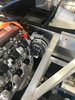
Very excited to get to this point and very satisfied how the LT4 fits.

Getting the engine in the frame, it was a little nerve racking since I’ve never done this before. Also, because of the geometry of the engine lift arm I found out that the engine shifts as you lower it so you can’t just place it where it needs to be and just lower it. So you lower it and adjust it, then lower some more and adjust it a few times but I got it in without swinging the engine into the frame rails.

Video of the engine installed in the chassis...

Lifting the engine above the frame...
829F775E-7EA5-45C1-9981-B20D6A3D39FF.jpeg


Lowering the engine...
C592424C-C960-4E49-A5F7-A9175DBB332E.jpeg


I decided to rest the rear of the engine on a wood rear engine mount stand. Since I am planning to make custom rear engine mounts that shift the engine back a bit I’ll use this to calculate exactly the shape and size of the rear mounts I’ll need to fab up. Plus having the car on a lift and the front engine mount in the chassis will easily allow me to get the engine perfectly level. Raising the lifts tilts the engine down in the back and vice versa.
28848244-C682-42F7-A963-098675571F5E.jpeg


The whole point of getting the engine in the car is that I know there are some fitment issues with the LT4 in the SL-C chassis. These being:

1)The need to fab up an intake elbow to reverse the throttle body
2)The alternator fouls the top frame rail

Most supercharged SL-C builds require a V cut in the rear bulkhead brace to make room for the throttle body intake elbow extension. I’d like to avoid that so my current thinking is to shift the engine back a little to make enough room for a custom elbow. By shifting the engine back about 1 to 1.5” I think there is enough room for the elbow. Since I am not building a track car the impact on handling should be minimal and not be a problem.

I have almost 4” clearance to fab up the intake by shifting the engine back slightly...
4A67210F-88C4-462A-B8C9-AA22C50E18D3.jpeg


1009A1DC-5797-40E0-B727-4DD1B0F31891.jpeg


Lastly, I thought about how to overcome the fact that the LT4 alternator fouls the top frame rail. Turns out the Sanden AC compressor has enough room, so I am going to swap the alternator and A/C compressor locations and everything will fit fine.

The wet sump version of the LT4 uses a low mount alternator. I ordered the alternator bracket just to see how it fits and it interferes with the water pump on the dry sump version so sent it back. It won’t be too difficult to fab the necessary brackets up. Wegner makes a top mount Sanden bracket for the Wet Sump LT4 with a dry sump water pump so I’ll check that out to see if it will work.

Pic of the alternator interference..
35769B01-2FE8-43FD-AA8D-48E73B832998.jpeg


Pice of the Sanden compressor and show there is enough room...
C413D90E-E4C6-46CA-94A2-AC0ECE895FB8.jpeg
 

Attachments

  • BAA993F3-A2A6-4DAD-8538-43D58E1F0390.jpeg
    BAA993F3-A2A6-4DAD-8538-43D58E1F0390.jpeg
    243.4 KB · Views: 325
Last edited:

Joel K

Supporter
Now that the engine is in the chassis I am focused on fabricating the necessary accessories to make the LT4 fit in the chassis. There are many accessory configurations and aftermarket brackets for LS engines but virtually none for the dry sump LT4 engine so I have to fab up a few items. I will say my fab skills have come a long way in a short amount of time. I enjoy this aspect of the build very much. Very challenging for sure.

The 1st accessory bracket to tackle is the bracket to mount the AC compressor where the LT4 high mount alternator goes.

I found a similar bracket listed in a complete LT4 accessory system from Wegner Motorsports. They have an accessory kit for a wet sump LT4 fitted with a dry sump LT4 waterpump and high mount bracket for a Sanden compressor. Here is a pic of the setup...
8BD3EC55-870E-4828-9062-01ADB2F5B8AE.jpeg


It shows that the compressor is 15.86” from the centerline from the engine and my frame is 32” wide so by fabricating up a similar bracket I could make the compressor fit in that location vs. having to modify the frame and leave the alternator up high.

So I printed out the bracket to actual size and made a template and constructed a plywood wood version of the bracket...

4CFBBA54-DE6D-4BFE-90CC-FDF667C0273D.jpeg


The bracket needed to be machined down in order to keep it thick enough to be strong and also line up the compressor pulley with the water pump pulley.
C3B3F428-3514-4958-B4DE-2136E915B641.jpeg

01B5D190-A39A-4AED-89E0-5A1E2CC51C5C.jpeg


The bracket bolts to the alternator bracket, looks pretty good...
BB2BF482-4F16-4DCB-99A6-341E03DBB848.jpeg


Making prototype brackets in plywood is nice since it is strong and easy to cut...
F4C24098-D57A-4D38-BB48-18912F277553.jpeg


Here is a video discussion on the approach in a bit more detail...
 
Last edited:

Joel K

Supporter
Now the hard part, fabricate the bracket out of billet. I have some nice tools, a light duty Mill and Drill, light duty band saw, etc. These tools were used to fab up the final compressor bracket. Here was the approach.

Used the plywood prototype bracket to make a pattern on the billet block. Use machine dye and a scribe to get a nice crisp line to follow.
F6D10324-5E00-4AAD-A627-211D497A2FE9.jpeg


Drilled holes where all the sharp bends are.This allows me to rotate the band saw blade when I got to those areas...
E76D64F7-F5E9-4AB9-9EA8-83377C7EA883.jpeg


Then used the mill and drill to machine down the recesses...
5EEDE13B-FA2D-471E-978B-6B324A5EE818.jpeg


Then finished the parts with using some different size sanding drums to smooth out the curved recess areas...
F5FD6AB9-4CB2-4C20-81BE-42CC832565EE.jpeg

1E9F33F7-E836-4341-9A0B-92F7B1BD0E39.jpeg


The billet bracket fits on the alternator bracket perfectly....
AF13425D-85CE-4183-A3E9-08F4192330EB.jpeg


Looks pretty cool...
46C27DD4-F2A2-4D58-AF20-43B94289EEF3.jpeg


Also machined up a lower bracket to insure the compressor mounts securely...
IMG_1235.jpg


The finished product..very satisfied with the end result...
11B521E7-A2F6-4CC7-8D68-0A6B2BB46FB2.jpeg


Compressor IMG_1243.jpg


Here is a video of how the bracket was fabricated...

Here is a video that show the finished product and how it mounts to the engine...

Next up is the throttle body intake elbow fabrication...
 
Last edited:
Back
Top