really a great build, love it.
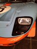
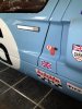
Those dzus are those more for period look?
A while ago I saw those types, they come in different forms and colors etc, will something like those Quik-latches also be possible to use on a GT40? they look besides handy also great me thinks.
Quik-Latch.com Your Authorized Dealer For Quik-Latch Products