
- Forums
- GT40 Replica Manufacturers' Corner
- RCR Forum - RCR40/SLC/917/Superlite Aero
- The SLC Clubhouse
You are using an out of date browser. It may not display this or other websites correctly.
You should upgrade or use an alternative browser.
You should upgrade or use an alternative browser.
Ken's SLC build thread
- Thread starter KENS80V
- Start date
I am not sure if this is going to be an issue with the Ricardo gearbox or not, but I would recommend that you put some sort of heat shielding between the exhaust and the gearbox, or make sure to cool the oil some how. The gearbox is going to act like a giant 220 lb heat sink, and that could cause some durability issues if the oil is allowed to run too hot.
Just a thought from looking at your pictures. Great looking build.
Erik Johnson
Just a thought from looking at your pictures. Great looking build.
Erik Johnson
Ken Roberts
Supporter
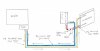
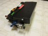
Here is a closer look at the problem AC fittings. The one that faces out (to the left in the picture) is the biggest problem. It aims right at the tub wall. I may try and make a box in the wall to get clearance.

It seems like the AC line that points toward the passenger tub wall is in the ideal position. Just drill a hole in the tub there and route the line back to the engine compartment. You have to drill a hole in the tub somewhere anyway.
Am I missing something???
Ken Roberts
Supporter
On the otherside of the tub wall at that location is the fiberglass bodywork. There is a bit of a gap in your favor though. That is what I will be researching soon. That line goes forward and connects to the lower side of the condenser.
Ken Roberts
Supporter
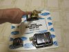
I had to cut the weighted puck off the end for muffler clearance. We might weld it back on at an angle now.
Ken Roberts
Supporter
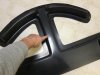
I might look into build a motor controlled door at the location I'm pointing to in the picture. The included knob with the AC unit has a unused "defrost" position on it. I wonder if Vintage Air would sell us such a motor. The door would remain closed in normal position to direct air to the dash vents only. Move the knob to "defrost" and the motor will open the door/gate to allow air to defrost the window. You would still need to shut the dash vents to mazimize the air to the window.
Attachments
Last edited:
Ken Roberts
Supporter
Here is a simple idea. I am not using the included servo heater control valve kit as shown in the picture. I will remove the water heater control valve from the servo (I'm pointing to it) and use this motor to control a door that I will install at the position I'm pointing to in the previous post.
UPDATE- I never ended up using this idea but others adapted it.
UPDATE- I never ended up using this idea but others adapted it.
Attachments
Last edited:
Here is a better picture of the AC lines.

Are you doing a "cool only" system or did you just leave out the heater coolant lines in your drawing?
Ken Roberts
Supporter
I just left them out as they are a no brainer....two 5/8 lines back to the waterpump.
Ken Roberts
Supporter
So why did you decide to not use the included servo controlled heater valve?
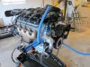
I am using a different type of heater valve located next to the engine. It fully closes the coolant flow and reroutes it back to the water pump when the AC is commanded on.
With the LS engine it has been reported that an over heating condition can occur if you start your engine with the AC on and you have the type of heater control valve that just closes off the coolant flow. It seems the LS engines need a constant loop of coolant flow through the heater pipes on the water pump.
Here is a picture of it connected to my engine in post #6 http://www.gt40s.com/forum/slc-clubhouse/38446-kens-slc-build-thread.html#post386379
Last edited:
Ken Roberts
Supporter
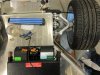
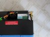
Here is a picture of the AC unit as it will be attached to the tub. It is on top of the tub for this picture to show how far the AC hose connections stick out the side wall. It mounts in the same position but just below and not above.
It will take some clever modifications to get this to work. Both AC hoses will need to connect on the outside of the tub.
It will take some clever modifications to get this to work. Both AC hoses will need to connect on the outside of the tub.
Attachments
Last edited:
Ken Roberts
Supporter
Ahhh yes, I remember reading about that issue during my GTM research. I am curious to know what type/brand servo controlled heater bypass valve you are using. The only heater bypass valve solution I have seen is a vacuum solenoid bypass valve.I am using a different type of heater valve located next to the engine. It fully closes the coolant flow and reroutes it back to the water pump when the AC is commanded on.
With the LS engine it has been reported that an over heating condition can occur if you start your engine with the AC on and you have the type of heater control valve that just closes off the coolant flow. It seems the LS engines need a constant loop of coolant flow through the heater pipes on the water pump.
Here is a picture of it connected to my engine in post #6 http://www.gt40s.com/forum/slc-clubhouse/38446-kens-slc-build-thread.html#post386379
Also, I was thinking more about how to "cleanly" integrate this A/C system with ISIS (assuming they do not already have a solution for this type of unit, which I doubt). If Vintage Air were to sell the Gen IV ECU, the Gen IV stepper motors (to control air flow and temperature), and a few other smaller individual components from the Gen IV system, the ISIS inVironment module could be used to control the system. Taking a look at the wire diagram for the Gen IV system seems like it could work.
Ahhh yes, I remember reading about that issue during my GTM research. I am curious to know what type/brand servo controlled heater bypass valve you are using. The only heater bypass valve solution I have seen is a vacuum solenoid bypass valve.
This bypass valve may be an option: Chevs of the 40s: OAP50-1555 - Heater Control Valve -Electronic
My LS6 motored "super 7" did not have heat and I capped off the inlet/outlets off the water pump. I never experienced any engine cooling issues. I've read both sides of the debates on this and still haven't found any definitive answer yet.... but, better safe than sorry. As always-your results may vary.
Ken Roberts
Supporter
My LS6 motored "super 7" did not have heat and I capped off the inlet/outlets off the water pump. I never experienced any engine cooling issues. I've read both sides of the debates on this and still haven't found any definitive answer yet.... but, better safe than sorry. As always-your results may vary.
Most (not all) sources I've seen say to loop heat in/out - it's a $5 hose loop at napa, so I just did.
Ken Roberts
Supporter
Thanks to work done by Dean we have a solution to the mounting of the AC unit. The top fitting/pipe (#6 line) can be rotated around by loosening the union. The bottom fitting/pipe can be bent in carefully to provide clearance from the wall. Then each fitting will get a 90 degree hose elbow (beadlock fitting). Here is a picture of how it needs to be changed.
Attachments
Last edited:
Similar threads
- Replies
- 5
- Views
- 1K
- Replies
- 1
- Views
- 2K