
You are using an out of date browser. It may not display this or other websites correctly.
You should upgrade or use an alternative browser.
You should upgrade or use an alternative browser.
Kiwi scratchbuilt
- Thread starter Russ Noble
- Start date
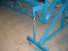
So not a lot done on the car, although I have started building a rotisserie to rebuild the car on. I used Lim's originally but he has it in use now. Winters coming up and I can't be bothered doing much on the car until the spring, by which time I expect to have rekindled my enthusiasm.
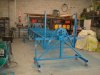
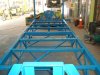
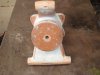
Well the enthusiasm is rekindled and the rotisserie was built over the winter.
I was fortunate to have most of the steel lying around. I got a pair of fwd Corolla rear hubs from a friendly wrecker for the table pivots. I had an old 351 flexplate and pinion that I am using to rotate it. I lashed out large on eight 250 kg braked castors to move it around on. Ex China of course, very well made, heavy duty, and cheap as chips.
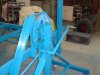
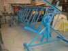
The turnbuckle stay dropping down from the side of the bed is to adjust it to dead level. I have a (magnetic) digital level which reads to +/- 0.05° and this will be ideal when setting anything perpendicular to the chassis bed. Or at any angle, if it comes to that.
The bed itself is dead square and true and held by triangulation. The two upstands at each end of the bed are perpendicular and in line with the front and rear of the bed. It will be very easy to measure from these datum points to make sure everything is in its correct position as the rebuild gets underway.
As mentioned earlier there will be some significant improvements/upgrades to the car. These will be mainly to incorporate some aero improvements. I will also be going up to 16 inch rear rim widths and there will be many smaller upgrades mainly for simplicity and to ease servicing. :thumbsup:
Unfortunately these upgrades will take more time than just doing a simple rebuild but they should make it faster still and more pleasant to work on. And that’s what it’s all about

I just can’t wait to get out on the track again.
 epper:
Damn. Photos didn't show. Patience...
Last edited:
SFOS this season is highly unlikely Brian. Just too many things that are going to be painstakingly slow.
First of these is that I have decided to make my own cast uprights for the rear. There are several reasons for this. Firstly the existing fabricated uprights both need major repair, this is time consuming anyway, and welding on the bearing housings distorts them. Repairing or building new fabricated uprights is extremely labour intensive every time. I figure that it is better to put the time into making patterns for casting which are then easily reproduced and only need machining. I don't expect them to be too much heavier than the fabricated steel ones, but time will tell.....
Also with regard to the fabricated uprights the shape requires altering anyway as my rear wheel backspace is going up from 5" to 6'' and I am also going to shorten the bottom leg of the upright so I can lift the bottom suspension arms in order to better utilise some form of diffuser at the rear.
Getting the wheels I need is another problem, but wheel problems and the solutions when I get them sussed, will be the subject a later post...
In the meantime, after reading up on making patterns for sand casting, (Lim was responsible for the sump, fuel caps, door handles etc used earlier) it is now my turn to have a go. I guess an upright is not the simplest thing to start with but I suppose that’s been the story of this whole build.
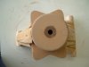
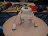
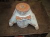
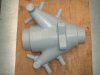
So, I have built the pattern for the upright allowing for shrinkage and having the minimum 1° taper in the required places. The rough shape has been laminated up from customwood sealed with fibreglass resin and then finally shaped and smoothed off with fibreglass body filler which is used also to form the radiused fillets.
Having got the shape the way I want it, it is now time to consult with the foundry on the sizes and positions for the projections for the core prints before I can finish off the pattern. Also to find out whether it would be better to use a mounted split pattern. I also need to school myself up a little on the details for making the core boxes. A quick visit to the foundry will hopefully clarify a lot of things in my mind.
I have lots still to find out and learn but considering a few weeks ago I really had no idea of the processes involved I’m reasonably happy with how things are going. Hope I can still say the same thing after I’ve had a chat to the foundry! There is still a lot of work to do though. I still have to make patterns for the cores and then make the core boxes. I can see this shaping up to a series of ‘warts and all’ posts.
Pics below are generally self explanatory of the work so far on the pattern
First of these is that I have decided to make my own cast uprights for the rear. There are several reasons for this. Firstly the existing fabricated uprights both need major repair, this is time consuming anyway, and welding on the bearing housings distorts them. Repairing or building new fabricated uprights is extremely labour intensive every time. I figure that it is better to put the time into making patterns for casting which are then easily reproduced and only need machining. I don't expect them to be too much heavier than the fabricated steel ones, but time will tell.....
Also with regard to the fabricated uprights the shape requires altering anyway as my rear wheel backspace is going up from 5" to 6'' and I am also going to shorten the bottom leg of the upright so I can lift the bottom suspension arms in order to better utilise some form of diffuser at the rear.
Getting the wheels I need is another problem, but wheel problems and the solutions when I get them sussed, will be the subject a later post...
In the meantime, after reading up on making patterns for sand casting, (Lim was responsible for the sump, fuel caps, door handles etc used earlier) it is now my turn to have a go. I guess an upright is not the simplest thing to start with but I suppose that’s been the story of this whole build.
So, I have built the pattern for the upright allowing for shrinkage and having the minimum 1° taper in the required places. The rough shape has been laminated up from customwood sealed with fibreglass resin and then finally shaped and smoothed off with fibreglass body filler which is used also to form the radiused fillets.
Having got the shape the way I want it, it is now time to consult with the foundry on the sizes and positions for the projections for the core prints before I can finish off the pattern. Also to find out whether it would be better to use a mounted split pattern. I also need to school myself up a little on the details for making the core boxes. A quick visit to the foundry will hopefully clarify a lot of things in my mind.
I have lots still to find out and learn but considering a few weeks ago I really had no idea of the processes involved I’m reasonably happy with how things are going. Hope I can still say the same thing after I’ve had a chat to the foundry! There is still a lot of work to do though. I still have to make patterns for the cores and then make the core boxes. I can see this shaping up to a series of ‘warts and all’ posts.
Pics below are generally self explanatory of the work so far on the pattern
Attachments
-
 DSCF1345 (640x480).jpg57.2 KB · Views: 612
 -
 DSCF1346.jpg87.7 KB · Views: 640
 -
 DSCF1340 (640x480).jpg58.5 KB · Views: 595
 -
 DSCF1339 (640x480).jpg59.2 KB · Views: 593
 -
 DSCF1338 (640x480).jpg71.6 KB · Views: 642
 -
 upright (3) (640x480).jpg78.2 KB · Views: 622
 -
 upright (5) (640x480).jpg84.3 KB · Views: 612
 -
 upright (640x480).jpg76.4 KB · Views: 667
Fantastic stuff, Russ. Did you say 16 inch rear rim widths? Wow.
Terry Oxandale
Skinny Man
Very Nice. I'm constantly being impressed on this build. Please enlighten me and explain the 1º taper requirement. Is this a casting requirement, or is this related to the application of the piece when finished?
Dalton, yes 16" rears. The main reason for this is I have been using 15.0 - 26.0 x 15 F5000 tyres which I can get for nothing. They are meant to have minimum 15" wide rims but I have been squeezing them down onto my 14s. However my source of tyres is now using 16.2 - 26.0 x 15 and the minimum rim width for those is 16". I think it is a bit much of an ask to squeeze those onto 14" rims. So new rims required, and since one of my 14s was buggered anyway, now is the time to change. But this is going to be a bit of a mission if I want to retain the traditional BRM pattern wheels. Watch this space.....
Terry, the 1° draft is a casting requirement but as I will be taking a fibreglass mold off them to enable the making of a split pattern, and also to facilitate making the cores, it will make releasing the mold that much easier also.
I talked to the foundry the other day and what I have done so far is fine and he was happy with where I planned to put the core projections. He did say though, that normally one makes the cores first and then builds the wall thickness up around them to give the final shape. Sounds logical, however for me it often seems easier to do things backwards!
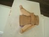
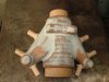
Below is a pic of the pattern with the core projections fitted. Final shaping, finishing, painting and waxing still to be done before taking off the mold. That’ll keep me going for a week or so yet.
Terry, the 1° draft is a casting requirement but as I will be taking a fibreglass mold off them to enable the making of a split pattern, and also to facilitate making the cores, it will make releasing the mold that much easier also.
I talked to the foundry the other day and what I have done so far is fine and he was happy with where I planned to put the core projections. He did say though, that normally one makes the cores first and then builds the wall thickness up around them to give the final shape. Sounds logical, however for me it often seems easier to do things backwards!
Below is a pic of the pattern with the core projections fitted. Final shaping, finishing, painting and waxing still to be done before taking off the mold. That’ll keep me going for a week or so yet.
Attachments
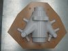
Pic 1.
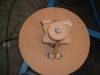
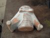
The upright pattern has been finally coated with Duratech and finish sanded and had the eight coats of release wax applied, ready for taking off a fibreglass mold. This will be done in two pieces split down the casting parting line.
Pic2.
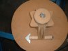
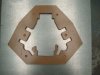
So I have had to make a fence to provide a joining flange along the parting line for the fibreglass mold. The round dimples around the outside are countersunk registers so that the two halves will bolt up exactly right.
The fibreglass will be laid up on one half of the upright and the fence, then when cured the fence will be removed and then the other half laid up to it.
Pic 3.
Fence in position on upright
The upright pattern has been finally coated with Duratech and finish sanded and had the eight coats of release wax applied, ready for taking off a fibreglass mold. This will be done in two pieces split down the casting parting line.
Pic2.
So I have had to make a fence to provide a joining flange along the parting line for the fibreglass mold. The round dimples around the outside are countersunk registers so that the two halves will bolt up exactly right.
The fibreglass will be laid up on one half of the upright and the fence, then when cured the fence will be removed and then the other half laid up to it.
Pic 3.
Fence in position on upright
Attachments
Last edited:
Terry Oxandale
Skinny Man
Very inspiring! Makes me want to search locally for a foundry.
Trevor Booth
Lifetime Supporter
Russ
why are you making a fibreglass mould, why dont you use the wooden pattern that you have made
if it was a production pattern from which many castings would be made yes , but not for a limited run
we have used plastic patterns (from a 3D printer) for limited runs
why are you making a fibreglass mould, why dont you use the wooden pattern that you have made
if it was a production pattern from which many castings would be made yes , but not for a limited run
we have used plastic patterns (from a 3D printer) for limited runs
Russ
why are you making a fibreglass mould, why dont you use the wooden pattern that you have made
if it was a production pattern from which many castings would be made yes , but not for a limited run
we have used plastic patterns (from a 3D printer) for limited runs
I'm with Trevor on this one. Why do you need to take a mould off your pattern. You make a pattern to make the mould from. You do have a split pattern?
Trevor Booth
Lifetime Supporter
Even if he does not have a split pattern it can be hand moulded , there are plenty of core prints , unless he is then using the fibreglass mould to make the core box by laying up in the female mould (cast from the wooden pattern ) the thickness of the finished casting and then making the core.
, unless he is then using the fibreglass mould to make the core box by laying up in the female mould (cast from the wooden pattern ) the thickness of the finished casting and then making the core.
That's exactly what I'm doing Trevor and that's the main reason for doing it this way. Also I can make up the split pattern from the molds as well.
It's good to have guys on board, on this thread and by PM, offering advice on easier/better ways of killing the cat. Thanks to all for your input.
Pedro (peguero) from Boston has suggested using plastic instead of fibreglass for the mold. Same method as doing the f/g halves except pour the plastic over and an hour later it is done. Sounds easier and quicker, I'll have to find out more about that. Maybe that could be a good option for molding the split pattern and the cores themselves?
Guess I've got a few things to quickly try and check up on.....
Trevor Booth
Lifetime Supporter
Russ,
why a split pattern , that is a very simple item to hand mould , put a groove across the end of the core prints on the parting line to give the moulder an accurate guide.
Good Old casting plaster to form the female mould is pretty easy and much easier to correct the double shrinkage that you will get.
Pouring plastic in to make core box would be difficult to achieve constant thickness. You could use a soft epoxy filler and boning rods or chaplets to get constant thickness. Also bear in mind that you need to rework the core box for the solid parts at the suspension pickup points and if you use GRP it will be difficult to work.
Soft epoxy fillers are used in the boat industry or you can mix fine ground french chalk into the normal "auto bog" however this tends to be very dry mix and a bit of effort to then mix the catalyst in. You can tool this with an exacto knife and carving chisels whilst it is going Off (and afterwards) to fix up the solid parts
I would also have a chat to your foundryman about joing some of the core prints, the larger the core print the more stable the core during the pour hence constant wall thickness.
Thanks for the input Trevor.
The foundry asked if I was going to do a split pattern. They seemed to think it would be better.
With regard to the core prints, I made them 22mm. I have an old F5000 McRae upright, which is not too dissimilar, cast by the same foundry and that uses 19mm core prints. I didn't want to go too big and risk weakening the upright.
The various suggestions that have been made certainly bear thinking about and could also be useful considerations for anyone else reading this thread and contemplating doing something similar. In the meantime I think I shall proceed generally as I originally intended. Unless I run into some strife.... which is of course highly possible..... :huh: Watch this space.")
The foundry asked if I was going to do a split pattern. They seemed to think it would be better.
With regard to the core prints, I made them 22mm. I have an old F5000 McRae upright, which is not too dissimilar, cast by the same foundry and that uses 19mm core prints. I didn't want to go too big and risk weakening the upright.
The various suggestions that have been made certainly bear thinking about and could also be useful considerations for anyone else reading this thread and contemplating doing something similar. In the meantime I think I shall proceed generally as I originally intended. Unless I run into some strife.... which is of course highly possible..... :huh: Watch this space.
Trevor Booth
Lifetime Supporter
Russ,
making the coreprint larger surface once outside the casting is what I was referring to. This can be independant of the actual hole in the casting left by the core. It is not uncommon to join them up with a trench in the core box hence providing a larger and more stable core print.. In foundry terminology the coreprint is the part outside the actual casting.
making the coreprint larger surface once outside the casting is what I was referring to. This can be independant of the actual hole in the casting left by the core. It is not uncommon to join them up with a trench in the core box hence providing a larger and more stable core print.. In foundry terminology the coreprint is the part outside the actual casting.
Similar threads
- Replies
- 10
- Views
- 829