Kiwi scratchbuilt

Russ Noble

GT40s Supporter
Lifetime Supporter
Damn, Jac Mac

I never thought about getting it out! :mad:

You should know better than that :D.

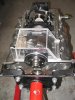
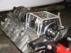
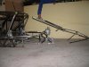
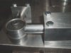
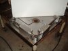
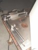
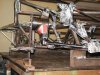
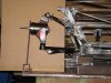
Actually the muffler will have to come off (2 bolts), then the whole rollcage backstay assembly which includes the crossbar between the shocks, and the rear body support framework, all one unit, has to be removed (4 nuts and 5 bolts).Then 4 bolts each on the front and rear motor plates and she's out. I removed the complete motor with plates, exhaust and trans last night in just a few minutes. Of course you still have to unhook fuel lines, drysump lines, electrical connections and throttle cable.

BTW you can't lay your hands on a VJ manifold that I can borrow for a week? 302, 351 doesn't matter. If you can, I'll pick it up next Thurs when I'm down your way.

Cheers
 

Russ Noble

GT40s Supporter
Lifetime Supporter
Russ,

are you planning on radius rod style rear suspension??

What do you plan on attaching to???

Looks really tight for an intake too.....no Webers for you ..eh!

That looks like a really easy tube chassis to repair...:p: .......I know..I know I couldn't resist...:dead:

Fran,

All these awkward questions.....

Yes, radius rods. You can see the part completed mounting points attached to the top of the chassis rail and the rollcage hoop. I have incorporated three alternative pivot points depending on ride height, antisquat etc.

Similar setup for the lower radius rods. Because of their outboard positioning I have gone to parallel links on the bottom rather than an A arm in order to eliminate the inevitable bump steer that would have otherwise occurred.

You know we kiwis can't afford Webers or injection! :rolleyes: 
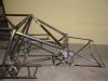
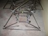
You're right about the chassis, but that's an irrelevant consideration coz it's never going to need repairing! :lol: :burnout:

Cheers
 
does that mean you are never going to finish it then?:D

I did notice your triple mounts but I am surprised you want them...
Seriously...I would expect that you have your geometry sorted and not need to make such drastic changes..

What is the reasoning behind such large increments
 
No , only have 302 VJ at moment ( not mine ) but will measure & scan dwg of various manifold heights ,& email to you tonite.
351w VJ is higher than 302w VJ anyway.

Jac Mac
 

Russ Noble

GT40s Supporter
Lifetime Supporter
Fran,

Sometimes I do wonder whether I am ever going to finish it...:mad:

The car is being built as a club car. Could be doing circuit work or Targa tarmac rallies. Ride height for each will be considerably different. For the track I am running 65mm ground clearance under the 930 bellhousing, for Targa I would be happier with 100 plus clearance. I would be running softer springs for Targa. If I want to raise the car an inch or two I can do it without cocking up all the suspension angles.

Jac Mac, Thanks, if a 302, I was just going to space it up as a dummy fit. Near enough for my purposes.

Cheers,
 
Last edited:
So I presume you will be making the inboard /chassis attachment points with the same three positions..so as not to compromise your camber gain ....?What about your roll centers, shock attachment points etc etc etc if not using new locations....??

There are so many small things to think about when designing your own set up and then actually making it happen with a clean sheet of paper takes some dogged determination....(I should know...jeez)....keep it up!!!!
 
Last edited:

Russ Noble

GT40s Supporter
Lifetime Supporter
So I presume you will be making the inboard /chassis attachment points with the same three positions..so as not to compromise your camber gain ....?

/quote]

Exactly Fran, you've got the picture. :) Raise the chassis an inch, drop all the pickup points an inch. Roll centres don't change, suspension still works within its designed range. Change the springs and maybe the shocks. The only thing is the mass centroid is higher, and driveshaft angles change, and you're getting more air under the car, but all that's pretty much unavoidable when you raise the car anyway. Compromises.....compromises....

Nevertheless I can't think of a better or simpler way to cover most of the bases, given the scenario.

Cheers
 
Russ,

if you are using CV joints make sure that the plunge in the shaft/joint itself does not become an issue....you already know this stuff...I will just be quiet....:eek:
 

Russ Noble

GT40s Supporter
Lifetime Supporter
Fran,

I appreciate you taking the time to comment.:) No need to keep quiet, there's always the thought that concentrating on the detail I've overlooked something horribly obvious and basic. :eek: Better to have it pointed out now than find out on the track.:)

Cheers,
 

Russ Noble

GT40s Supporter
Lifetime Supporter
Well, Lim has undertaken to cast the sump (as well as doing the majority of the machining required for this build). There are several criteria for this sump...
1 I want to keep it as shallow as possible.
2. It needs to allow the use of a LHS front mounted 928 starter to work on the small 930 ring gear.
3. Because there is the thought that we could possibly sell a few of these precision made kiwi castings it needs to accomodate the largest stroke possible bearing in mind the other criteria.
4. It must clear 4 bolt caps.

So the mounting of the 928 starter is the limiting factor and Lim has decided to make a mockup of the rear section of the sump in perspex so we can see and measure the clearances that we have before making the actual pattern.

We are aiming for a wall thickness of about 6mm, any thicker is too heavy and any thinner makes it difficult for the molten alloy to flow satisfactorily.
So the actual pattern is going to be crafted in 1/4'' steel plate. It looks as though we can build this sump to accommodate 4.1, maybe even 4.25, strokes, depending on components used.

Below are some shots of the perspex mockup, the actual full pattern will of course have radiused corners etc where required.
 

Attachments

  • perspex sump 1.jpg
    perspex sump 1.jpg
    33.5 KB · Views: 1,555
  • perspex sump 2.jpg
    perspex sump 2.jpg
    144.6 KB · Views: 1,603
Last edited:
Russ/Lim,

When you make your pattern up to do the castings, make a clip in insert for the rear main cap half circle so that you can cater for both 351 & 302 versions. That is the only real difference between the two apart from the attach bolts adjacent to the rear main cap, but you should be able to add enough material to cover both types in that area.

Jac Mac
 
Russ, if you get the time, could you please post some details and photos of the casting process? I have done some backyard casting myself (not implying that is what Lim is doing) so I understand the process, but it is not something often covered on the forum and therefore might be of interest to members.

Thanks - like the idea of a perspex pattern!
 

Russ Noble

GT40s Supporter
Lifetime Supporter
Jac Mac,

Thanks for that input. Will do. And thanks for the manifold dims.

Richard,

Will do that too.

Cheers
 

Russ Noble

GT40s Supporter
Lifetime Supporter
Since you mentioned it Jac Mac.......

Here's the rear chassis and removable subframe.:)

Cheers,
 

Attachments

  • Chassis 033.jpg
    Chassis 033.jpg
    40.6 KB · Views: 1,580
  • Chassis 034.jpg
    Chassis 034.jpg
    48.5 KB · Views: 1,486
  • Chassis 029.jpg
    Chassis 029.jpg
    37.8 KB · Views: 1,433

Russ Noble

GT40s Supporter
Lifetime Supporter
Some pics of the front bottom arm. Sitting in the jig about to be welded up
 

Attachments

  • fr lwr ball housing.JPG
    fr lwr ball housing.JPG
    61.4 KB · Views: 1,338
  • front lwr arm jig.JPG
    front lwr arm jig.JPG
    78.6 KB · Views: 1,345
  • lower wishbone jig.jpg
    lower wishbone jig.jpg
    21.8 KB · Views: 1,339

Russ Noble

GT40s Supporter
Lifetime Supporter
The lower arm went through three different iterations before I was happy with the design. Mainly the shock mounts and rim clearance issues. The first one I built was just used to play around with.That's the one at the back. From there the first real attempt is the middle one. And the final refinement shown in the front .

These arms are shown upside down, the shock eye is below the arm not above it
 

Attachments

  • lwr arm iterations.jpg
    lwr arm iterations.jpg
    37.1 KB · Views: 1,477

Russ Noble

GT40s Supporter
Lifetime Supporter
And here's how it all looks bolted in place.

I wanted to get to this stage so I could measure the actual motion ratios front and rear and calculate spring rates. I needed to do that before I could order the shocks and the valving required and the springs.

Whilst having different wheel rates front and rear, it is possible to design the suspension so that the same spec shocks and springs can be used at either end. The bonus is that I only had to order one spare shock which will work equally well front or rear. I have ordered five 8212 series Konis from Gordon Levy. The theory is that I'm only going to knock one corner off at a time..... This could be a flawed theory! But if I take out more than one corner in any one incident, I doubt we'd be going for the next race anyway!

The four springs, all identical, are being made to my specification here in Christchurch by Chamberlain Springs.

The following pics show a bar bolted to a spacer on the front upright. The bottom of the bar represents the mid point of the bottom of the wheel. The chassis is sitting with maximum droop ground clearance, and incremental one inch spacer blocks are placed under the bar to simulate suspension movements every inch up to full bump. The shock length is recorded and the motion ratios calculated. The overall motion ratio is used to determine springs and shock valving but I wanted to check it incrementally to see how it changed over the range.

In the pics the suspension is sitting as it will at race ride height.
 

Attachments

  • Front Motion Ratios 013.jpg
    Front Motion Ratios 013.jpg
    64.2 KB · Views: 1,502
  • Front Motion Ratios 020.jpg
    Front Motion Ratios 020.jpg
    48.4 KB · Views: 1,421
Last edited:

Russ Noble

GT40s Supporter
Lifetime Supporter
Alloy flywheel from 7075 billet and steel friction plate from H13 billet machined by Lim to take 7.25" clutch and Porsche 930 ring gear positioned to suit front mounted 928 starter motor. Nice, small and light assembly. :)

Threaded the ring gear bolt holes so it could attach by cap screws from the rear. Pics show nine holding screws a la Porsche but will probably only use six or maybe three. Yet to decide. Heads of the clutch cover/friction plate retaining bolts are recessed and captive in the front of the flywheel. Have balanced all attachment bolts/screws to +/- 0.1 grams.
 

Attachments

  • Flywheel 002.jpg
    Flywheel 002.jpg
    42 KB · Views: 1,077
  • Flywheel 004.jpg
    Flywheel 004.jpg
    19.7 KB · Views: 1,055
  • Flywheel 005.jpg
    Flywheel 005.jpg
    40.6 KB · Views: 1,003
  • flywheel recess 029.jpg
    flywheel recess 029.jpg
    34.4 KB · Views: 987
Hi Russ,

I love reading the thread, to me the design and construction of the frame is the single most important thing in building a car, its a shame it never gets the oh's and ah's a shiny set piece of fibreglass gets.

Looking at the pictures it looks as if most of the chassis and other parts are bronze welded whilst others (uprights for example are not). Would it be possible to explain the reasoning behind that to us?
 

Russ Noble

GT40s Supporter
Lifetime Supporter
Doug,

You've got a good eye for detail. Mind you I'd expect that from a fellow scratchbuilder!

The main chassis frame was built on a jig round at Lims where he has a tig. Lim actually did the tigging on the main frame. I don't have a tig at my place so am using high strength Nickel Silver Bronze. I used this on a spaceframe that I built up years ago and found it most satisfactory. Despite some high speed, high impact crashes I never had a Nickel Silver joint let go. A chassis tube might tear apart somewhere along it's length but never at the join. Also with brazing generally you don't actually melt the parent material thus don't change its properties. The Nickel Silver penetrates the joint by capilliary action. Basically anything that is tigged has been done by Lim anything brazed is my handiwork.

There is one other reason for my not using the tig and that is because I lost an eye a few years ago and I have no 3D vision. Thus I cannot tell whether I am undercutting the weld. This is obviously undesirable and weakens the tube. That doesn't happen using the Nickel Silver because the tube does not become molten. That is also why some of the brazing looks like a dogs breakfast, because I can't tell whether I am getting a consistent build up. The joints will be plenty strong enough, they just look ugly. For certification purposes we are not allowed to dress the welds. They have to be inspected "warts and all" and unpainted. Paint later on will do wonders but it's pretty frustrating at times....

Cheers
 
Last edited:
Back
Top