KVA Type C Mk1 Build Log 943motorsport.

Thanks for that.
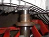
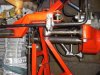
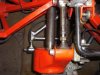
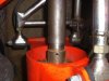
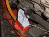
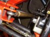
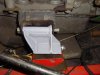
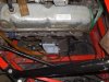
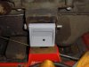
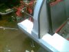
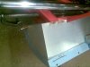
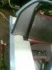
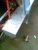
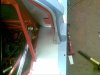
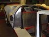
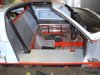
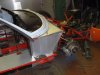
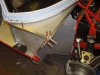
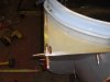
I have made up some spacer blocks to get the ride height correct. I then made some tubes with a RH and LH thread in them and fitted rod end bearings to replace the shockies, This then allowed me to get the hubs to the correct height but still have the car raised off the floor to allow me to work easier. I have made up a shaft to simulate a drive shaft with a clearance fit at both sides. which will fit into the recess in the renault to ford drive shaft adaptor on the gearbox side. I have fitted another adaptor to the hub side in reverse which the machined shaft fits over. It has allowed me to get the gearbox set to the exact height so as to have the driveshafts perfectly straight when the car is at normal ride height. I have had to angle the engine down by 1 deg to allow the rear clip to clear the oil filler cap etc etc. Does this sound resonably?

Will try and post some pictures tommorow
 

Mike Pass

Supporter
One degree is fine. Most GTDs have the engine down by up to 4/5 degrees. If you want the carb level make up a wedge shaped spacer plate to sit under the carb.
Cheers
Mike
 
Someone above mentioned Canton Oil Pans.

I also recommend Canton. I bought a baffled and kicked out road race pan and Acusump from them. Very easy to deal with and the pan is a work of art.

PM me for the contact details of the UK Agent if you like.
 
Have decided to just modify the standard sump and add some capacity to it , may have to modify the pickup pipe , but have never seen inside the ford V8 before so will be an adventure.

Will post pickture later tonight of my progress so far.
 
Photos so far.

Engine mounts have been made but require drilled in the correct place, may weld them on when I have the position set 100%. I also may have to put a stay on the angled one. I have also shown the bar which was made up to align the gearbox to engine. It is not lined up correctly in the photos as I had to move the engine a bit to do other work but you will get the idea. engine mounts have also been drilled for an earth cable to bridge the rubber mounts. Any comments welcome.
 

Attachments

  • Forum post sept 09.jpg
    Forum post sept 09.jpg
    50.8 KB · Views: 542
  • Forum post sept 09 (2).jpg
    Forum post sept 09 (2).jpg
    39.3 KB · Views: 542
  • Forum post sept 09 (3).jpg
    Forum post sept 09 (3).jpg
    56.1 KB · Views: 543
  • Forum post sept 09 (4).jpg
    Forum post sept 09 (4).jpg
    45.7 KB · Views: 489
  • Forum post sept 09 (5).jpg
    Forum post sept 09 (5).jpg
    37.3 KB · Views: 486
  • Forum post sept 09 (6).jpg
    Forum post sept 09 (6).jpg
    41.7 KB · Views: 457
  • Forum post sept 09 (7).jpg
    Forum post sept 09 (7).jpg
    43 KB · Views: 470
  • Forum post sept 09 (8).jpg
    Forum post sept 09 (8).jpg
    48.5 KB · Views: 489
  • Forum post sept 09 (9).jpg
    Forum post sept 09 (9).jpg
    31.3 KB · Views: 458
Hi Robin
Your engine mounts look fine, I reccomend that you drill and bolt them to the chassis, this will give you more space for future engine removal and refits etc, also will give you the abillity to shim up the motor for final alignment etc.
When you modify your sump take care not to foul the handbrake cable ( IVA test).
Your attention to drive shaft angle is very worthwhile, the granada shafts,when running up wards to the hubs are very close to the max length when the suspension is on fuull bump on the KVA type C.
Good luck with your build,check out Monkeyboy KVA mk 3 build log for more pics etc,
cheers
John.
 
I agree with the handbrake cable issue. I have marked the sump where the handbrake cable touches and will either modify the sump or modify the curved equaliser bracket to increase the angle to allow it too clear. Does the sva take into account items like this?. Have just printed out the full IVA guide/manual but have not read it fully yet. It keeps putting me too sleep when I try!!!
 
Hi Robin,
The IVA test is to be taken seriously, any foul of mechanical parts will result in a fail. On the KVA i partly restored for monkeyboy there were alot of issues to put right to enable the car to take the then SVA test. The KVA was designed years before any serious testing procedure was even thought of. From my own experiance check steering lock so tires dont foul inner arches, check front suspension on full drop for straining (necking) of ball joints ,Take photos of seat belt anchorages (hidden when tanks are fitted), make sure all brake pipes are fastened to chassis at correct intrvals, ensure all lights and windscreen are E marked,
Hope I have not put you off your stride but many car builds stall due to buiders not being aware of the rules, also keep ALL the paperwork receipts etc to enable you to succesfully register the cer when complete.
cheers
John.
 
Started on replacing the gear linkage tonight. The linkage that came with the car was OK but thought it could be a bit better. Rather do it now than when the car is finished. Unfortunately things never worked out quite right. Have made all the linkage up with 1/2 rod end bearings and have two universal joints in the shafts. Linkage all works fine with positions and length of levers etc etc, But there is just too much spring in it. Used 1/2 stainless steel bar , guess this is not the correct material too use, any advice on the grade of steel too use. ?? Thanks will post pictures tommorow.
 

Brian Magee

Supporter
Robin

I don't think the grade of steel is the problem, just the thickness. You need to go up to 5/16" rod. If you still want to use the 1/2" rod ends use the 1/2" bar through joints then go up to the 5/16" for the long runs. To join them bore out the ends of the larger bar to 1/2" then drill through the two to take a 6mm cap head bolt. Drill out one side of the outer bar to accept the head of the cap head. The head will then clamp against the inner bar and give you a solid joint with no play and you can still take it apart to assemble it.

Brian.
 
Thanks for that. I thought you meant 5/8 so never said anything. I have some 1/2 rod coming that is used for linear bearing shafts to trial not stainless but a very hard strong steel so will give it a go as it will not cost me anything. Will let you know the progress. Thanks.

Going to the Brisca Formula 2 World Final this weekend so no posts for a day or so. !!!!
 
Well my couple of days off turned into a few more. Bought an enduro motorbike a couple of weeks ago to try and have a go at a few enduros, Not been on a bike for Twenty years so a bit of a culture shock, However on holiday from work for a week so time to get stuck into the car again , Will continue with the gear linkage tommorow and get the engine out on Tuesday, This will allow me to start on the paneling, Full steam ahead!!!!
 
Going back to the granada driveshaft issue that I questioned earlier in the post. I have just had a check at a granada shaft and it seems around 100mm too long, can anybody tell me if the granada shafts are different lengths on either side, Dont know what side the shaft I measured was from, Need to be around 420mm from what I can measure, . Gear linkage now done and most of the rear bulkhead panelled, Now working on the panelling around the front wheel arch and along the side above the tank, Will post pictures tommorow.

Thanks in anticipation of your help
 

Ian Anderson

Lifetime Supporter
Robin

Also try a VWcamper Type 2 driveshaft

About the same length and CV bolt circle is the same as the Ford

Ian
 
Pictures as promised,! I have not started on the panels around the handbrake etc as I have not decided what too do here. Some of the panels in the pictures need the edges finished and I have applied a covering of clear vinyl to protect them until completion, This is the material I use for applying signwriting vinyl and found it very handy and very cheap for a 25meter roll. Have also found a supplier in Scotland for All your alloy and stainless steel requirements which i found very resonable, at £27 for a 2.5M X 1.25M sheet of 1.5mm, I can pass the details on if required.
 

Attachments

  • Forum Post October 09 (2).jpg
    Forum Post October 09 (2).jpg
    53.8 KB · Views: 510
  • Forum Post October 09 (3).jpg
    Forum Post October 09 (3).jpg
    57.3 KB · Views: 485
  • Forum Post October 09 (4).jpg
    Forum Post October 09 (4).jpg
    24.6 KB · Views: 532
  • Forum Post October 09 (5).jpg
    Forum Post October 09 (5).jpg
    18.3 KB · Views: 457
  • Forum Post October 09 (6).jpg
    Forum Post October 09 (6).jpg
    52.8 KB · Views: 489
  • Forum Post October 09 (7).jpg
    Forum Post October 09 (7).jpg
    36.9 KB · Views: 456
  • Forum Post October 09 (8).jpg
    Forum Post October 09 (8).jpg
    48 KB · Views: 493
  • Forum Post October 09 (9).jpg
    Forum Post October 09 (9).jpg
    42.1 KB · Views: 542
  • Forum Post October 09 (10).jpg
    Forum Post October 09 (10).jpg
    41.1 KB · Views: 535
  • Forum Post October 09 (11).jpg
    Forum Post October 09 (11).jpg
    26.7 KB · Views: 429

Brian Magee

Supporter
Robin,

Normally the bottom half of the panel behind the front wheel is upright then comes forward at a sharper angle. Might be worth checking wheel clearance at full compression before you go too far.

I am taking an interest in this car as it went through my hands earlier in its life.

Brian.
 
May just be the photos but the bottom of the panelling is flush with the steelwork of the car and cannot go any further back, do you think this will be ok?
 
Back
Top