Not a bad idea...the rest of the house has car parts, might as well include some in the kitchen too. lol. I'm mostly concerned about it's long term stability, but I'm going to go ahead and run them. Good news is they're cheap. If it doesn't last 5 years I'll replace.Hard to know if you aren't sure of the material... best way is to test it. My wife loves it when I use kitchen appliances for experiments. A 15 PSI pressure cooker with get to 250 F which is about the right temp. I'd drop it in and cook it for a couple of hours and see what happens. I'd be more worried about a plastic smell than it melting. If you don't have one you can get a new one from Amazon for $49

You are using an out of date browser. It may not display this or other websites correctly.
You should upgrade or use an alternative browser.
You should upgrade or use an alternative browser.
LBC Build Log - Apex
- Thread starter LBCportagee
- Start date
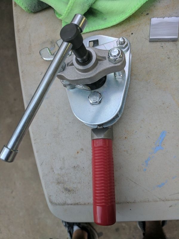
I got a new style of tool for my 37' AN flares, and I like it. Its a Parker Rolo-Flair. I picked it up from aircraft-tool
Can't really see the flares but they're good. I just use cheapo harbor freight bending tools and they work fine for me. I'd like a swagelok though.
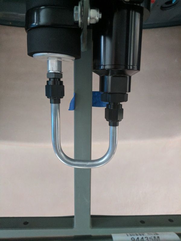

Can't really see the flares but they're good. I just use cheapo harbor freight bending tools and they work fine for me. I'd like a swagelok though.

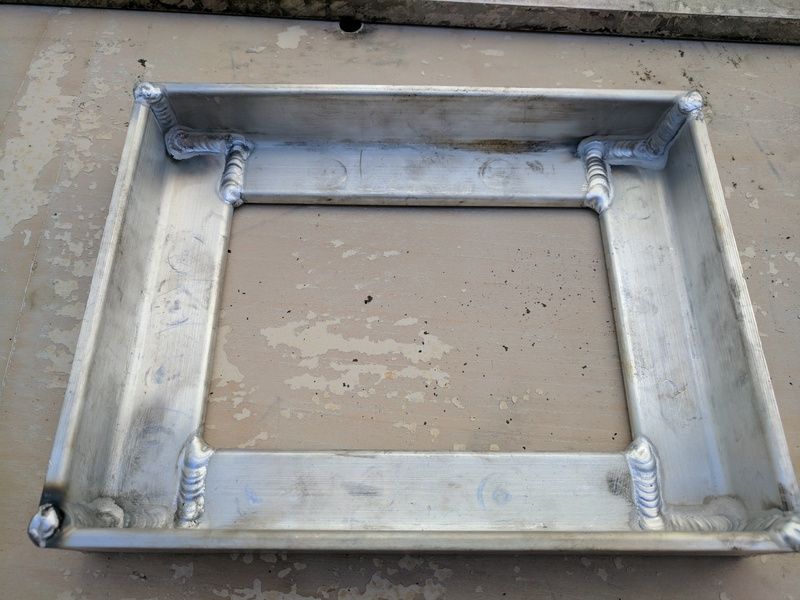
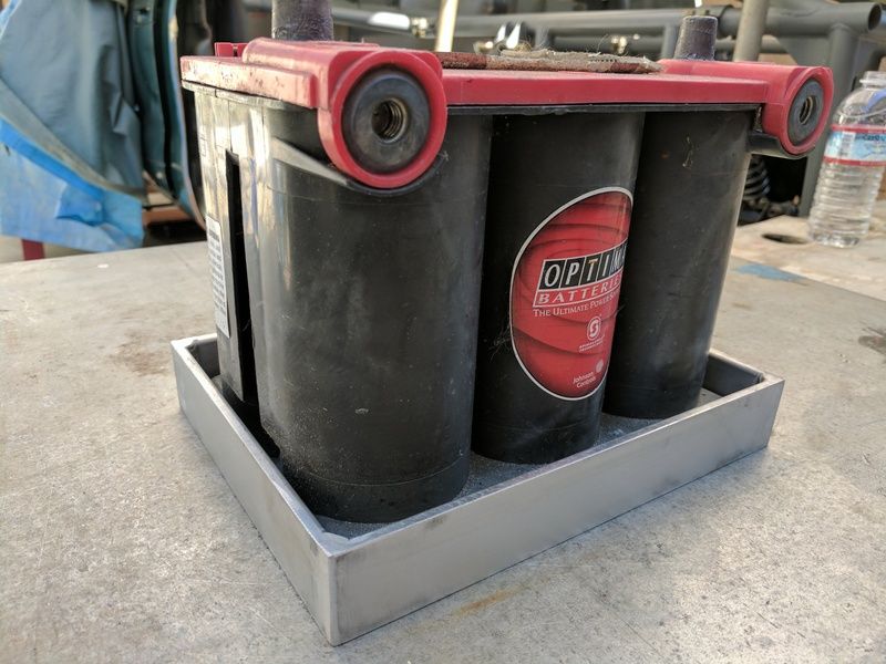
Small start on the battery box


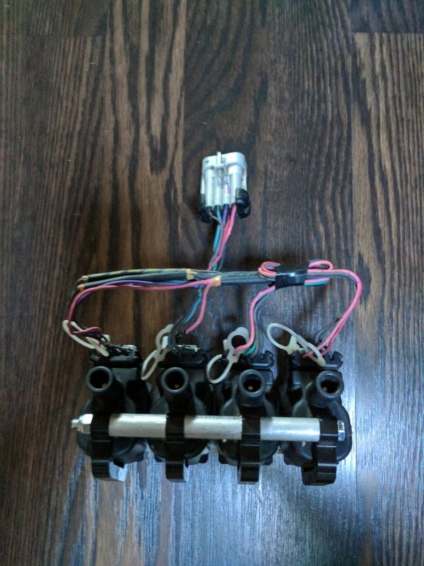
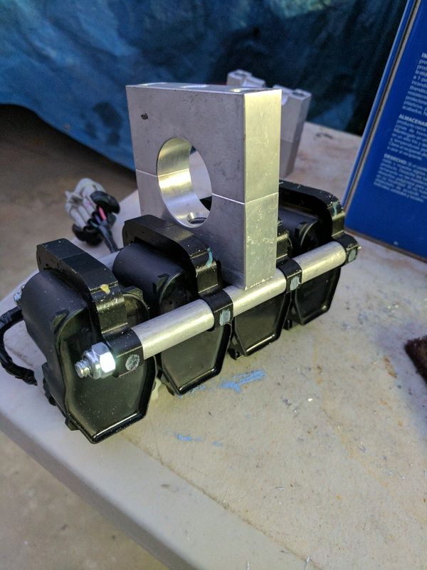
Throwing together some remote mounts for the coils. Debating whether to just wrap this with split loom as is or rewire a new harness to fit.

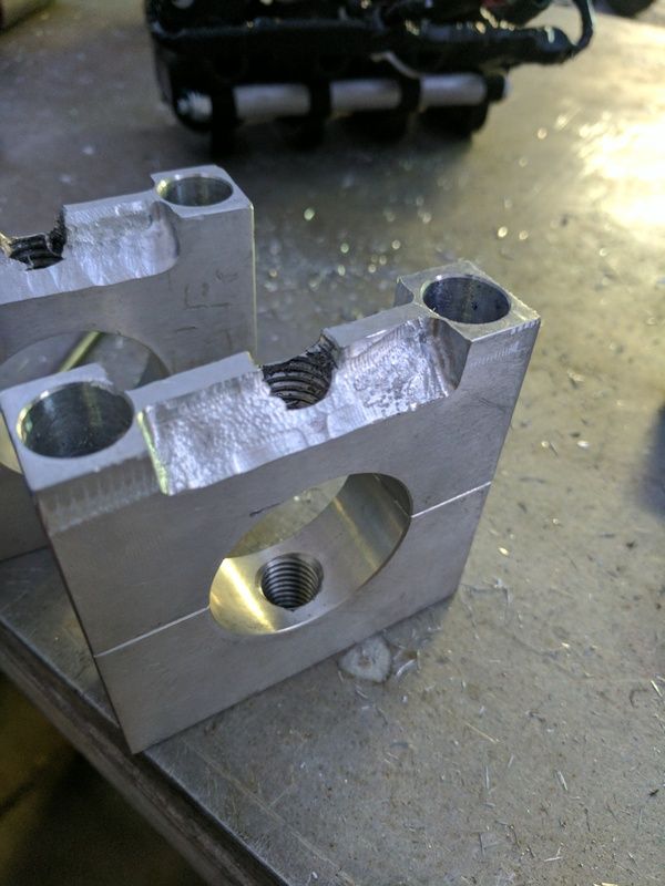
Decided to resurrect the aluminum mounts I bought to mount the rcr steering rack. A little grinding and they should make a good mount to the tube frame. This is when you wish you had a mill... aluminum shavings can suck.


Surge tank ready to be anodized (a good idea with ethanol), after I get some mounts welded on.
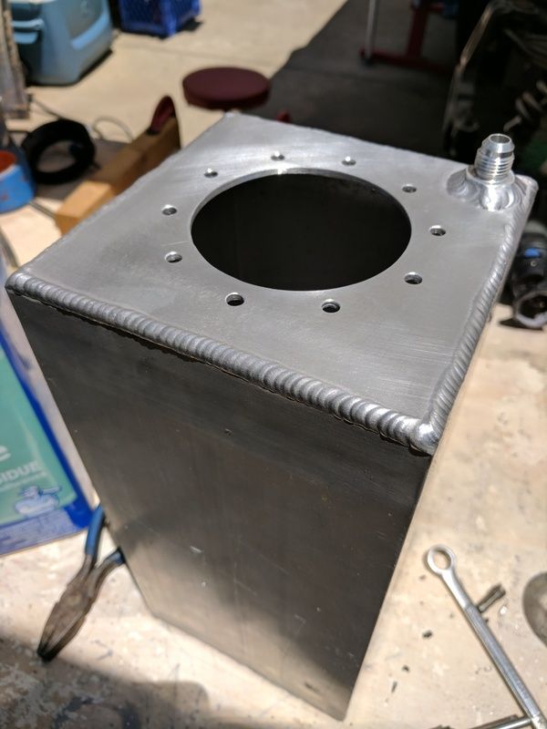
I decided to switch to an in-tank pump on the surge tank since real estate is somewhat sparse in the Apex - well actually there's lots of room just no where to mount anything. The flat surfaces on the SLC would be nice. The pump will be an Aeromotive stealth and does 340lph so should be enough for E85.
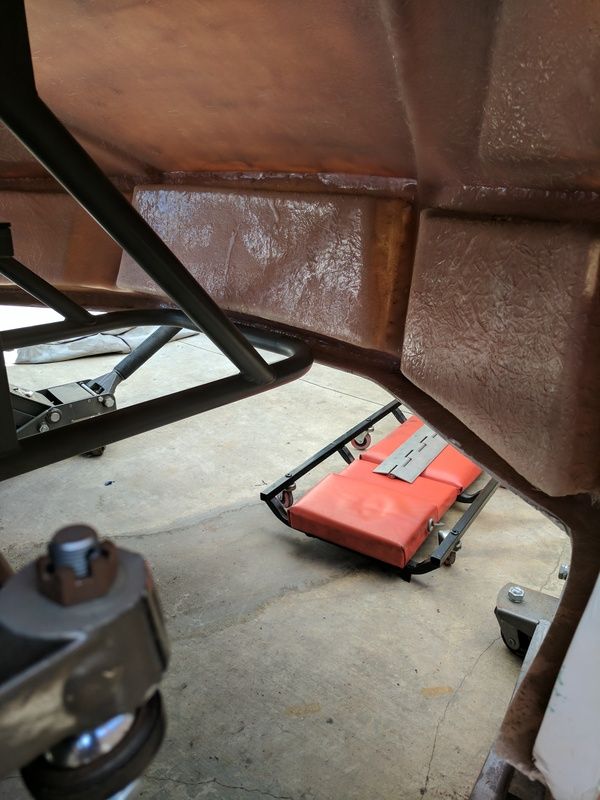
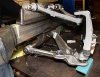
Really I need to put the engine in so I can determine where everything will go and I almost did that today...then I thought about the amount of body work that is going to be required (and the mess) and figured I'd tackle at least the major fitting first. So I'll see you in a year or two. No but seriously today I was just staring thinking WTF am I going to do with this. lol Starting with the easy part, the front end. The issue is it's not meant to open...at all. And there's very little actual subframe upfront...see pic. I first thought I'd just cut a hood out and build some drip channels which would be manageable but I wasn't hugely excited to cut a third of the front end off. Then I saw Glen was going to use a piano hinge by cutting just behind the front wheel's and the entire front body would swing forward...made sense. Only with the entire body swinging there's nothing to support the body to. Which basicaly leaves you with 1/3 of the body on each side unsupported. Thats not going to work. I can build a lightweight triangulated frame to support it better, but the only place this can attach to is the hinge because it needs to rotate with the body. So I think I could add a latch just in front of the front tires maybe so that I can tie the triangulated body frame into the front subframe. This presents a final issue, the undertray (and wheel wells really). If its attached to the body it must swing clear of everything (frankly not happening). If its attached to the middle subframe, how do you keep the air below it or keep it from fluttering. I'm wondering if I should go back to a hood.
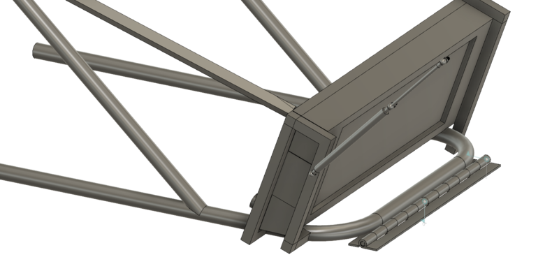
An idea what hinge will look like. A lot here is not to scale, just messing around with ideas also for radiator.

I decided to switch to an in-tank pump on the surge tank since real estate is somewhat sparse in the Apex - well actually there's lots of room just no where to mount anything. The flat surfaces on the SLC would be nice. The pump will be an Aeromotive stealth and does 340lph so should be enough for E85.
Really I need to put the engine in so I can determine where everything will go and I almost did that today...then I thought about the amount of body work that is going to be required (and the mess) and figured I'd tackle at least the major fitting first. So I'll see you in a year or two. No but seriously today I was just staring thinking WTF am I going to do with this. lol Starting with the easy part, the front end. The issue is it's not meant to open...at all. And there's very little actual subframe upfront...see pic. I first thought I'd just cut a hood out and build some drip channels which would be manageable but I wasn't hugely excited to cut a third of the front end off. Then I saw Glen was going to use a piano hinge by cutting just behind the front wheel's and the entire front body would swing forward...made sense. Only with the entire body swinging there's nothing to support the body to. Which basicaly leaves you with 1/3 of the body on each side unsupported. Thats not going to work. I can build a lightweight triangulated frame to support it better, but the only place this can attach to is the hinge because it needs to rotate with the body. So I think I could add a latch just in front of the front tires maybe so that I can tie the triangulated body frame into the front subframe. This presents a final issue, the undertray (and wheel wells really). If its attached to the body it must swing clear of everything (frankly not happening). If its attached to the middle subframe, how do you keep the air below it or keep it from fluttering. I'm wondering if I should go back to a hood.

An idea what hinge will look like. A lot here is not to scale, just messing around with ideas also for radiator.

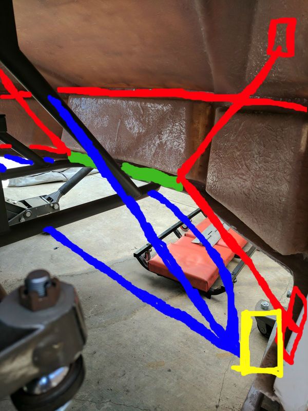
Because my description previously was somewhat difficult I thought I'd make matters worse with the poorest photoshop pic ever. Anyway Hinge in green, Red triangulated body support, blue tie-in to subframe, Yellow latch somehow between blue and red.

Haven't truly got anything done lately. This is another thing I'm contending with preventing me from moving forward. I can't decide if there's something wrong with the geometry/placement of the control arm mounts or what is going on.
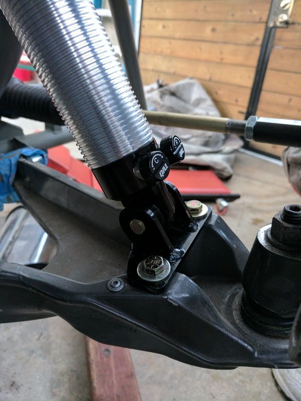
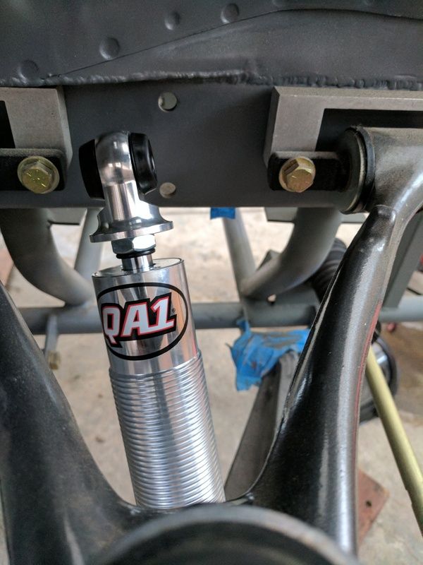
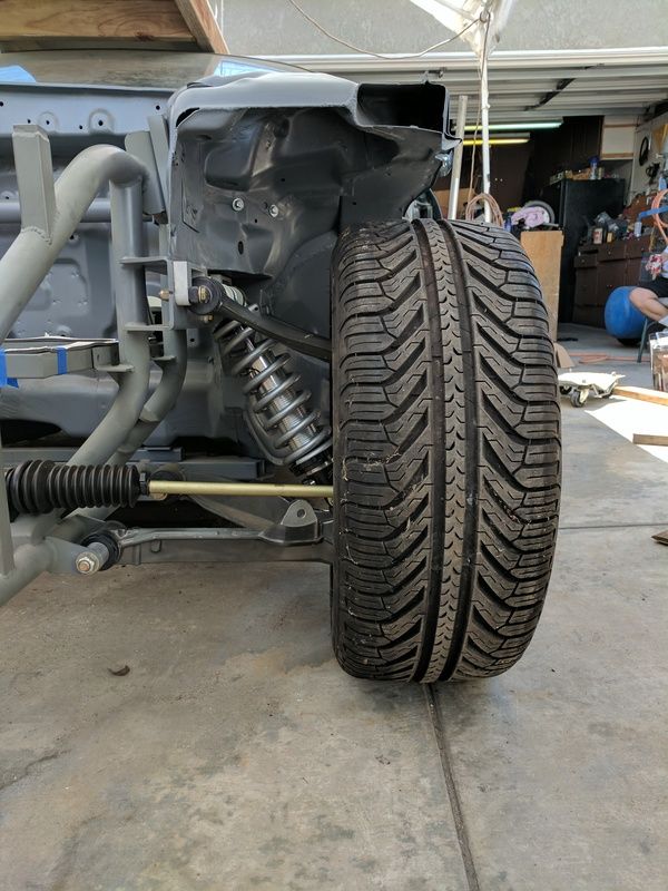
The lower coilover bracket is basically a square piece (90's). Its what the factory five GTM mount the coilovers to for their corvette suspension. There are no angles created with the bracket. But once attached to the lower control arm the coilover is pretty far from aligning with the coilover mount location. I can move the LCA forward but that will increase caster (I'm going to try a rough calculation this weekend to see where we are), but more importantly it will not change the angle the coilover is at. It should be upright. I know I can create a new lower bracket with angles that will correct this (won't be pretty or ideal), But I'd like to know the cause. Other cars are not like this. Also not seen in the pic, the upper control arm ball joint angle doesn't seem right, it's already at an angle with the upright at rest. I haven't set ride height yet due to these issues and I think the springs are too long but I'll remove them and place the LCA at estimated ride height and attach a pic also.
The lower coilover bracket is basically a square piece (90's). Its what the factory five GTM mount the coilovers to for their corvette suspension. There are no angles created with the bracket. But once attached to the lower control arm the coilover is pretty far from aligning with the coilover mount location. I can move the LCA forward but that will increase caster (I'm going to try a rough calculation this weekend to see where we are), but more importantly it will not change the angle the coilover is at. It should be upright. I know I can create a new lower bracket with angles that will correct this (won't be pretty or ideal), But I'd like to know the cause. Other cars are not like this. Also not seen in the pic, the upper control arm ball joint angle doesn't seem right, it's already at an angle with the upright at rest. I haven't set ride height yet due to these issues and I think the springs are too long but I'll remove them and place the LCA at estimated ride height and attach a pic also.


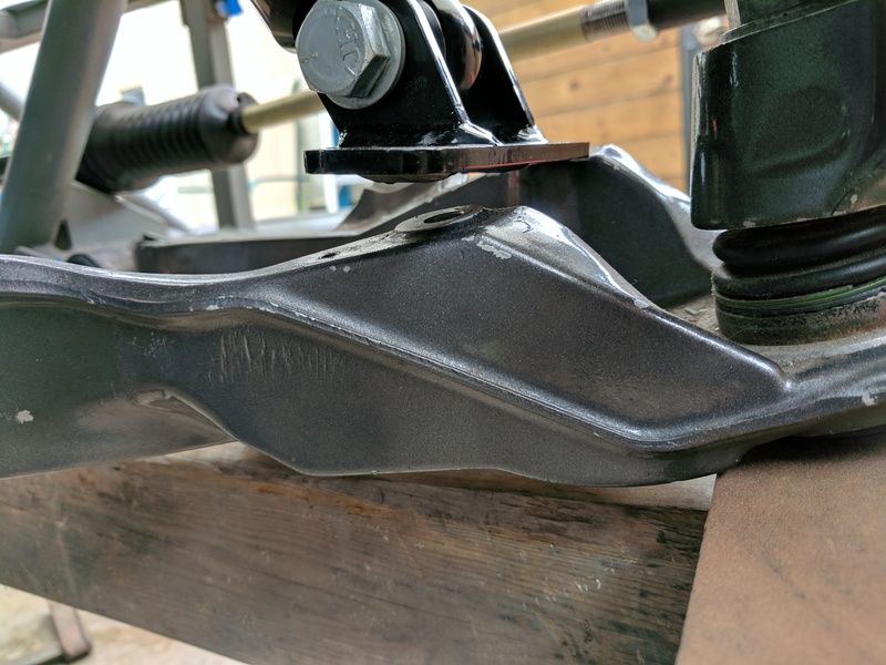
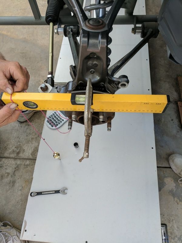
Today I set the lower control arm at level with the frame of the car. My goal was to see if I needed to change my control arm spacers and add-in some caster that might help align the coilover (would be marginal help at best). But I couldn't even get past an initial measure of camber at this estimated ride height. It was a half bubble off - positive camber (I need a new battery in my angle finder or I'd provide the actual #). I hoped ride height was just too low, but as I jacked up the suspension it made no change to the camber. The problem - there is no way to build in negative camber on this design, only to go more positive. The upper control arm is kissing the frame, it can't move in more. The lower control arm is mounted to the tabs RCR welded to the frame. Those tabs have holes drilled at the end of them. If you drilled out the holes, there would be no material left. I can't put my finger on it but I'm pretty sure something wasn't constructed properly on this subframe. This is getting tiresome. Perhaps they didn't account for the standoff that's required for the upper control arm knuckle. The only way around it is to cut holes in the 1/4" steel plate for the knuckles to fit into...then you could do away with the standoff and decrease camber.
This is the clearance I'm talking about on the UCA.
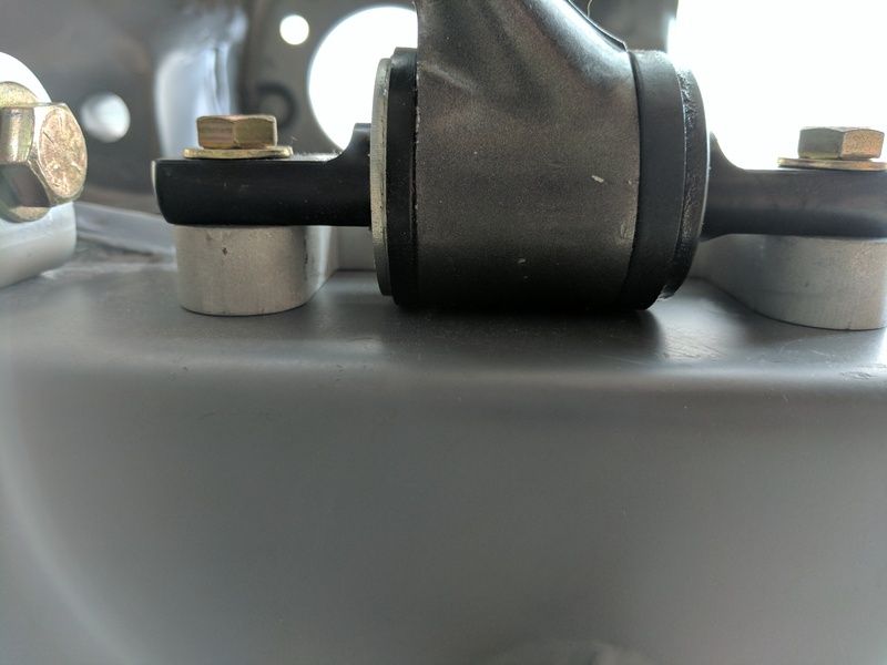
another look at the gap I'd need to fill
and from the top
excuse the old hub I'm not going to be using...I didn't even get to use my super accurate caster turn plate yet.
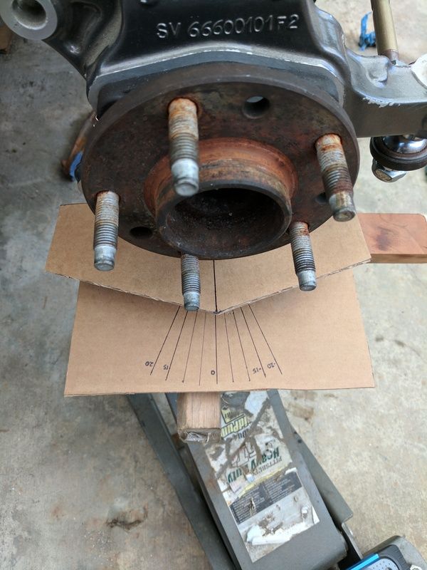
Anybody ever do measurements like this (estimating ride height and do prelim alignment without wheels) and find positive caster....but then actually get negative caster when the car is finally put on the ground?
This is the clearance I'm talking about on the UCA.

another look at the gap I'd need to fill

and from the top

excuse the old hub I'm not going to be using...I didn't even get to use my super accurate caster turn plate yet.

Anybody ever do measurements like this (estimating ride height and do prelim alignment without wheels) and find positive caster....but then actually get negative caster when the car is finally put on the ground?
Scott --
Not being able to see a good top and side view pic of the LCA, I have to ask if they could possibly be reversed (wrong sides).
I have done initia lalignments like you are doing many times and had good success. There will be some compression of bushings with weight on the suspension, but it is negligable in the affect on the alignment settings.
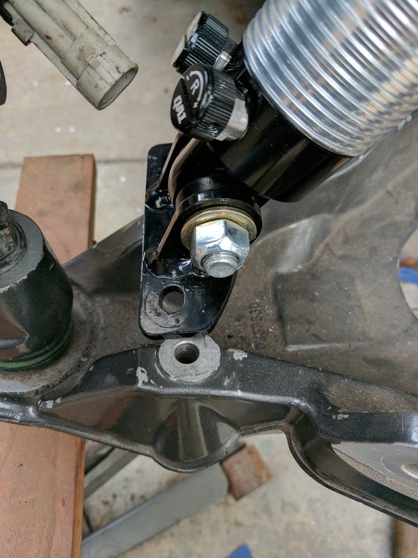
As far as the lower shock mounting adapter is concerned, I would toss those mounts in the bin and make new ones, or at least cut off the ear that is too short and weld a longer one on to get the proper attitude of the lower shock bolt.
Is that the UCA that is resting on the chassis? If so, shim that up slightly.
You are doing well considering the hand you were dealt here.
Not being able to see a good top and side view pic of the LCA, I have to ask if they could possibly be reversed (wrong sides).
I have done initia lalignments like you are doing many times and had good success. There will be some compression of bushings with weight on the suspension, but it is negligable in the affect on the alignment settings.
As far as the lower shock mounting adapter is concerned, I would toss those mounts in the bin and make new ones, or at least cut off the ear that is too short and weld a longer one on to get the proper attitude of the lower shock bolt.
Is that the UCA that is resting on the chassis? If so, shim that up slightly.
You are doing well considering the hand you were dealt here.
Frank Clark
Supporter
When I've done that my on the ground numbers were as accurate as my ride height approximation would allow. If the numbers change I would look for deflection somewhere.
Scott --
Not being able to see a good top and side view pic of the LCA, I have to ask if they could possibly be reversed (wrong sides).
Thanks for taking a look. The sway bar mount is towards the front of the car on the front suspension LCA. The proper orientation as far as I'm aware.
I was afraid it wouldn't help much. I can make new mounts and figured I'd have to, but since Glen's car doesn't have these issues I wanted to make sure I wasn't just missing something. Everything is just mounted in RCR's mounting points. Hard to screw it up...well. I just wonder how many other geometry attributes are screwed up, that a work around bracket isn't going to correct. That was really my only hesitation from moving forward but I guess I'm going to have to.but it is negligable in the affect on the alignment settings. As far as the lower shock mounting adapter is concerned, I would toss those mounts in the bin and make new ones, or at least cut off the ear that is too short and weld a longer one on to get the proper attitude of the lower shock bolt.
The shot is from below. Hard to see because its dark but it does swing clear of touching the frame and can squeeze in card stock behind without touching. I also realized when looking at the photo though that with bushing flex I could have contact. I'll have to shim slightly but will worsen camber. I'm likely to have to cutout out rectangular holes there anyway to recess the control arms past the frame.Is that the UCA that is resting on the chassis? If so, shim that up slightly.
Scott, the Corvette w/bones in factory application have a considerable amount of anti dive built into the mounting points on chassis, whoever designed/built your chassis ignored this and that is the cause of your lower shock mount problem, its also likely that the lower w/bone chassis mounts need to be redone. Pic attached.
PS, pm me with your email if you require further explanation, for some strange reason the moderator of this forum seems to like removing posts by me on his forum.
PS, pm me with your email if you require further explanation, for some strange reason the moderator of this forum seems to like removing posts by me on his forum.
Attachments
I agree that the lack of anti dive makes it more difficult to achieve the camber goals I would want and probably the coilover mounting, but mounting the UCA and LCA level is definitely a suspension strategy over an oversight I'd say. Not everyone would agree with the approach necessarily and would depend mostly on whether the car was for street vs track. The GTM is a clear example of a "shared" strategy using the same suspension. However I'd say my issue is more of a lack of care in making this particular sub frame since the issue is not shared with another Apex. That's no better than an engineering failure IMO though (however this could be both).
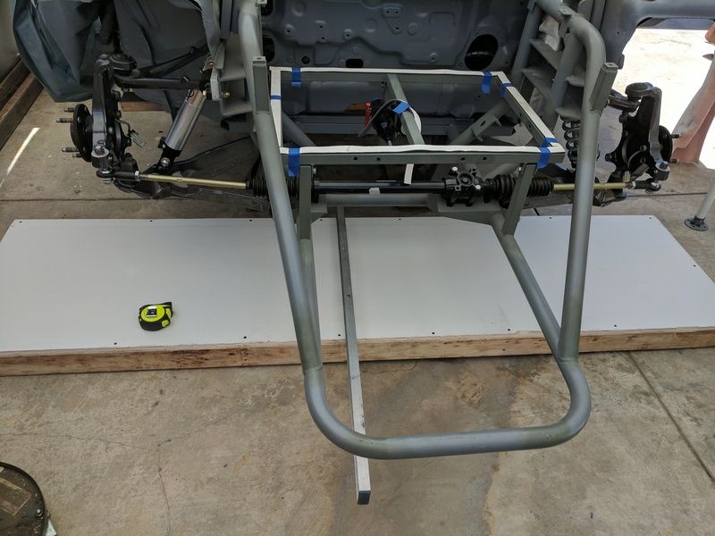
At any rate, I've decided to spend a little bit of time in Suspension Analyzer 2.4 (Performance Trends), and see if I can optimize this setup with as few changes as possible. Because there is little room to make changes I can input these limits in the software for the best available results...hopefully since this will be a first. So the next couple days will be spent with a plumb bob and sheetrock.
At any rate, I've decided to spend a little bit of time in Suspension Analyzer 2.4 (Performance Trends), and see if I can optimize this setup with as few changes as possible. Because there is little room to make changes I can input these limits in the software for the best available results...hopefully since this will be a first. So the next couple days will be spent with a plumb bob and sheetrock.
The take away from measuring chassis and suspension's is that it is not fun. After building the base and leveling we got through one side of the front end plus a couple other measurement on the other side in a day. There's a lot of ambiguity in estimating the exact location of ball joints on three planes but we did best... anyway what we found I think was somewhat promising. Alltogether measurements were pretty consistent from one side to the next. Our issue is mostly stemming from the subframe mounting plate for the upper passenger side control arm. It is 1/4" different from centerline then the driver side that's currently correlating to a difference between 0 camber and positive 1.3' camber between the sides. Also not good considering we cannot go to negative camber without cutting into the subframe mounting plates. I could live with zero, but we'll have to remove about .1857 material and then machine down our shims by the same amount just to match that zero on the driver side. If we really want negative camber we'll have to do both sides. I still can't say what the issue is with the coilover mount....whatever.
I'm now currently having issues with the optimizer function on the suspension analyzer. I'll run the suggested improvements then show a graphical comparison of the old vs new with dive,roll, steer constraints and it looks like things get worse. I'm missing something.


I'm now currently having issues with the optimizer function on the suspension analyzer. I'll run the suggested improvements then show a graphical comparison of the old vs new with dive,roll, steer constraints and it looks like things get worse. I'm missing something.
Attachments
I think the easiest solution for the coilover is to go back to a t-bar mount, similar to the original corvette. This will have to be paired with a bearing style coilover instead of the bushing type (you remove the bearing and just use the eyelet with the tbar). These shocks needed to go back anyway, it will need to be shorter, since this appears to only have about 3/4" travel at ride height currently which you can see in above pic. Also will need at least 9" springs instead of 10".
This is from QA1

This is from QA1
1st attempt to put engine in. The Corvette oil pan doesn't fit the rear subframe.
Our preliminary measurement was before Superlite made changes to move the engines forward. Now it no go. Mostly irritated that I had to clearance the transaxle adapter plate for the lower bolts into the oil pan that will now be going. O well.
Our preliminary measurement was before Superlite made changes to move the engines forward. Now it no go. Mostly irritated that I had to clearance the transaxle adapter plate for the lower bolts into the oil pan that will now be going. O well.
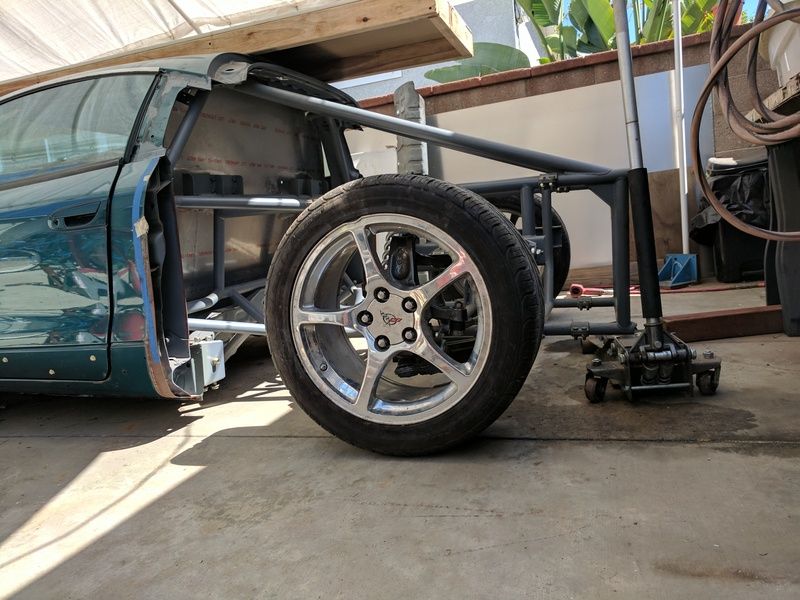
Couple of pics of car on ground confirm the need for shorter springs and shocks in front and longer springs and shocks in back.


Frank Clark
Supporter
I have a bat-wing pan if that may solve any issues for you. PM me if interested.
Similar threads
- Replies
- 1
- Views
- 474
- Replies
- 10
- Views
- 2K
- Replies
- 12
- Views
- 1K