LBC Build Log - Apex

I have a bat-wing pan if that may solve any issues for you. PM me if interested.

Thank you for the offer. The c5 pan we tried was actually a bat-wing. The wings are what kept it from fitting. Will try an F body pan, but I think it will be too deep. We'll have to cut the subframe I believe.
 
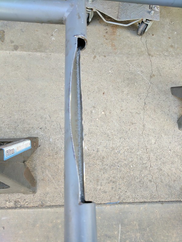
I bought the smallest rear sump oil pan I could find which was the holley swap pan (302-1). Still interfered with the cross bar on the subframe. I thought I'd leave as much of the bar as possible but I ended up cutting out more then half to give minimal clearance. This to allow the engine to finally sit on top of the sold mounts....which don't line up. The mounts are about 1/4" too wide. I either need to heat the subframe and see how much I can get the solid mounts to move. Or clearance holes on the engine mounts to see if I can move them into place without them being in a bind.

I think there might also be a solid mount height/angle issue on top of the width. If I choose to put in either the right or left motor mount bolt, I cannot put in either of the transmission/adapter plate bolts to their subframe mount...I tried loosening the adapter plate from the engine and they still could not be coerced in. Mounts must be too high.
 
Here is the modification we made to the cross bar to fit oil pan. We'll either strengthen this or cut it out completely and replace with smaller tubing.
IMG_20170714_165726 by LBCportagee, on Flickr

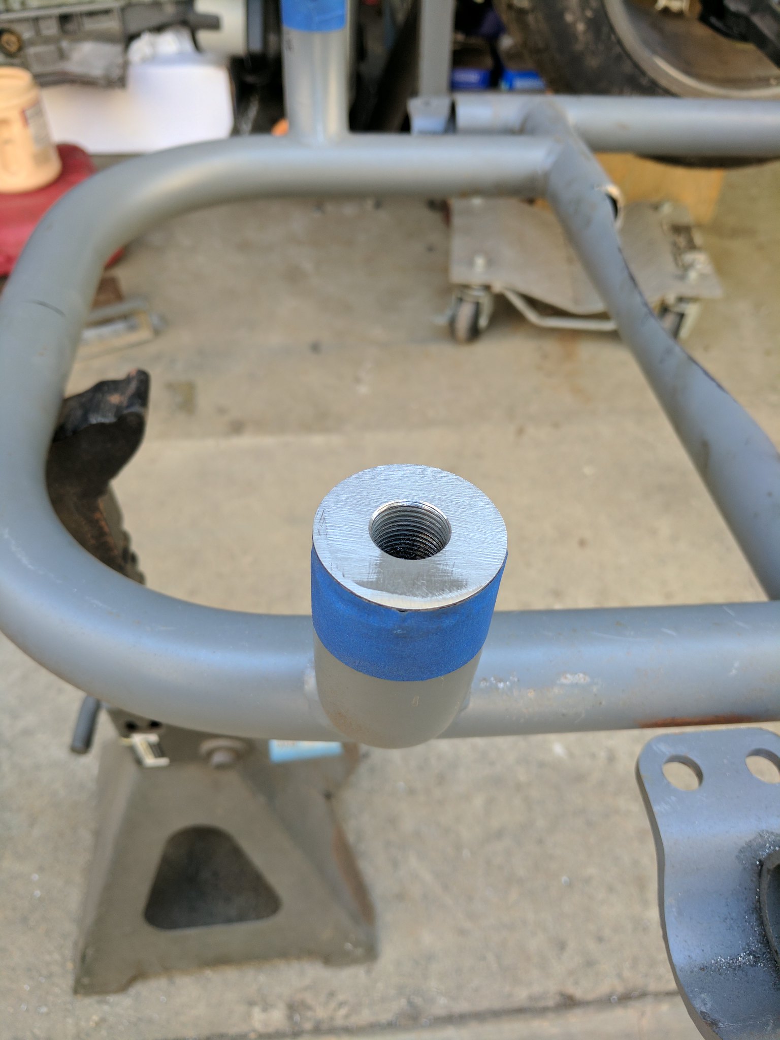
Also had to take down both front motor mounts to get the adapter plate to bolt to the transaxle mount. This one is also off by about 1/4" so it will need to be bent into place. We will take a cut out, heat, pound and weld into place, or at least thats the plan.

IMG_20170714_165736 by LBCportagee, on Flickr
 
I do have quit a few odds and ends of 1 1/2" dom with bends, so I'll see if I have something that works...what I don't have is the threaded plug to weld in. It's so close that I wasn't really considering cutting off the mount alltogether but you're probably right. I think the angle of the threading would be an issue after bending it too. I feel like I need a shortcut here and there though.
 
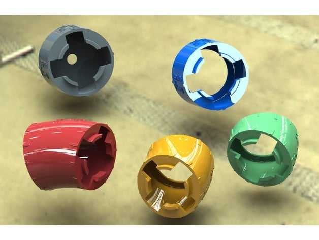
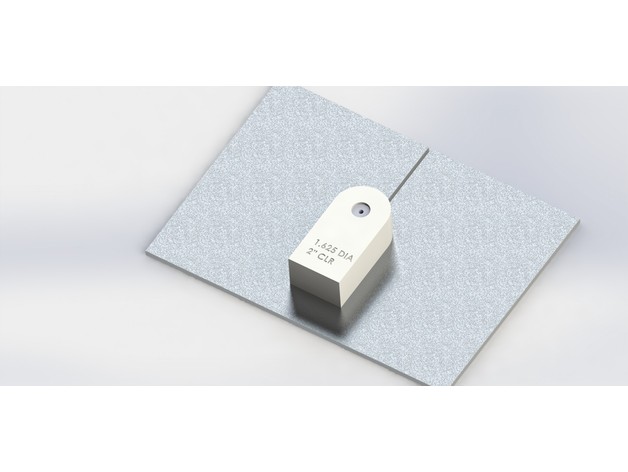
Just wanted to share a link for those interested in Fabricating your own headers (and owners of a 3D printer). I think these parts will immediately be recognizable (and also the thought "Oh those would be nice if it weren't for the $$$$). The STEP files are posted in various sizes and CLR which is good because it's not that easy to re-engineer a different size off of the step file and maintain the CLR. The band saw cutting tools are only available in 1-5/8" though, but I created 1-3/4" and 1-7/8" in various CLR in like 30 minutes. There's also 3" for mocking Exhaust routing. Available at Thingiverse

b5e0b2d5fc83a0400cab87bdae62614d_preview_featured.JPG

84d0f4edf5f9866e8eb570c5b0953b94_preview_featured.JPG

icengineworks-4-tube-mockup.jpg
 
This project has been put away for awhile (kids & a move) and I was sort of dreading making the major changes required (or the money it would take to throw at it). But the goal is to just work on it and use as many of the parts purchased years ago as I can to keep costs down. Case in point is the Coilovers and springs that were purchased from Superlite (you know, trying to make things easy). However, the Coilovers in the back were several inches to short (and the springs themselves were an inch shorter then recommended for the coilover). The opposite problem in Front, several inches to long. So that was the first thing tackled and didn't cost $1500 to replace the parts. Maybe beefier then needed.
PXL_20210320_231723715.jpg

PXL_20210322_021418713.jpg

PXL_20210322_021410910.jpg
 
Next up, the motor and trans mounts. The engine and transaxle has to drop several inches and that will be to get the CV angle to about 15 degrees. Not great but will hopefully do.

The Apex was designed with the rear body fixed. There's no rear clam or opening. So a "cradle" was made where the engine and trans could be removed as a package on the rear wheels. To support the cradle requires bars crossing under the engine/trans. So all these crossover bars have to be cut out and made to angle down making room for the engine to be dropped a 2-3 inches.

IMG_20170702_163105.jpg


The especially fun part of this is that the cradle wasn't designed correctly and WILL NOT come out with an LS attached. You must first remove the transaxle. Separate the engine from the cradle within the car, then pull the cradle out the side. Then drop the engine onto a cart or something then pull that out the side. Further...None of this will likely be possible with a "permanent" body attached. Basically the rear body has to be made removable for the engine to ever come out again. If I'm going to paint the chassis and brackets etc when I'm done with everything...it all WILL need to come out again.
 
Started to work on the fueling system. The challenge here is there isn't a lot of real estate to attach things. My goal was to try and use the tube chassis to mount rather then adding a lot of material in the open space to have mounting surfaces. Again using parts and fitting I already had, so some of locations/routing might not be ideal but should work.

These brackets are pretty simple using angle iron welded to tube chassis.
PXL_20210429_034652553.jpg


Here are the tanks attached to the brackets...these are the coolant and overflow tanks we made. The lower tank is the surge tank we made...The bolts on the surge tank are for the Ethanol % sensor to be attached directly. Also made the mounts for the fuel filter/water seperator (white) and the fuel pressure regulator. This location is partially dictated by some 90' fittings attached to fuel rails (what I had, otherwise I would have needed to buy 4x 120' fittings for cleaner/closer install).

PXL_20210430_074746574.jpg
.
 
Started working on the fan shroud. The radiator supplied by superlite is the one used on their gt40s. It's not the ideal size and the mounting points arent great...but going with it. I'm using 1/16" aluminum for the duct. The shroud could have been thicker material...but I have 10' of this sheet. So instead of welding we're riveting 1" angle to close the ends and support. Would have also liked the shroud deeper but this is what fits. Debating if plasma cutting holes will warp this....
PXL_20210522_190730500~3.jpg


PXL_20210522_191048805~3.jpg
 
About as close as I can get the radiator. Just need to build the frame to mount it. Duct will run up the angled bars. Not sure how I'm going to "seal" it to the top of the body yet.

PXL_20210613_024718790.jpg
 

Howard Jones

Supporter
I would build down to it from above with a section of closed-cell foam that is covered with fiberglass. The foam is designed to adhere to fiberglass and is very lightweight for its volume. Once you have a close fit to the body you can seal it with one-sided sticky flexible foam tape. While you are at it form the inlet side to best control airflow into the radiator.
 
This is the water pump mount we came up with. The tubes it mounts to are in three different directions and the pump doesn't fit within them. So this was just a quick solution with square tube. Clearance is meh.
PXL_20210701_020158954-01.jpeg

PXL_20210701_020508344-01.jpeg

PXL_20210701_020712396-01.jpeg
 
Been lucky to finally get some free time to work on this. Just wrapped up the mounts for the radiator. Really was a function of the space constraints and lack of mounting surfaces. Will tie in one more spot later that will double as the body shock mounts as well.
PXL_20210724_001530655-01.jpeg

PXL_20210731_005430703-01.jpeg
 
I might’ve missed it elsewhere in your build log…will you be using a system to control PWM features? That pump is PWM capable, and I’ve been looking at going PWM with water, fuel, and cooling fans. Built a PWM watercooled PC and love the ability to set curves that offer quiet for low demand and plenty of output for high demand.
 
I might’ve missed it elsewhere in your build log…will you be using a system to control PWM features? That pump is PWM capable, and I’ve been looking at going PWM with water, fuel, and cooling fans. Built a PWM watercooled PC and love the ability to set curves that offer quiet for low demand and plenty of output for high demand.

I'll be using a Haltech Nexus R5. Its an ECU/PDM and should make the setup of the PWM pretty straight forward. This handles 8a up to 12v through PWM so that overcomes the 5v issue many have using arduino's etc. to set these pumps up. I've included a page from Haltech on the 8a & 25a outputs.
 

Attachments

  • HAL_R5_8aHCO.pdf
    43.9 KB · Views: 195
Back
Top