
You are using an out of date browser. It may not display this or other websites correctly.
You should upgrade or use an alternative browser.
You should upgrade or use an alternative browser.
Mclaren M8b replica (visual)
- Thread starter russell keach
- Start date
Hi
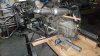
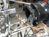
Just a little more progress, got both headers completed and one side right thru to the muffler and tail pipe. This car should have a little more attitude as I am using slightly shorter mufflers, really want to hear that sound. Once all the dirty cutting and grinding is finished, I will reassemble the front end and do a semi preliminary fit out and make it look more like a car. Then its strip down again for paint.
Cheers
Attachments
Terry Oxandale
Skinny Man
Nice job Russell. So, how's the rear uprights coming along?
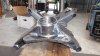
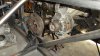
The rear uprights are still sitting on the bench like the proverbial jig saw puzzle waiting for a clear run. Once I have the exhausts done that`s the next major bit of wrangling. Looking at the folded plate that I will fabricate them from, I am wishing that I had made full cardboard mock ups and got the bits lazer cut, it sure would have save a lot of grinding. I have already turned up the bearing housings and welded the brake caliper mounts on, these also form the foundation for the bottom and top arms. Next week should see some progress.
Cheers
Cheers
Hi,
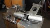
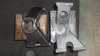
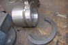
Finished my rear uprights...and these could end up being the most fettled paper weights I own if my engineer can not bore them out true. Despite taking as much care as possible and keeping the body / hub thick at around 11mm thick, I have ended up with significant distortion or shrinkage. Provided he can grip them, we may be able to save them.
Such is life.
Cheers
Attachments
Hey Russell , Looking pretty dam good from here, engineers are really magicians if he cant save them, he could always make them disappear to my place lol. I like the hammer glaze finish, was it from a rattle tin, if so what brand did you use looking pretty good.
I had a similar problem with mine (not near as fancy as yours), the machinist had to make a fixture which he tackwelded to the upright and could then grip in the chuck. It looks like you have a nice shoulder on the one end that he can use as a starting point to locate the fixture so you should be right. Apart from damaging the paint of course :thumbsdown:
Cheers
Fred W B
Cheers
Fred W B
Last edited:
Terry Oxandale
Skinny Man
Russ, Good looking pair of uprights. Can you post a weight for these? They certainly don't look heavy by any means.
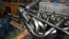
Both exhausts now ready to play a tune.
Question for JacMac. Do I put in a ` balance` pipe and what is its effect?
Cheers
Balance pipe 'should' be prior to mufflers and an 'X' pipe would be preferable, in the 'too hard' basket without re-arranging your mufflers/tailpipes I think.
Balance pipe evens out ex pressure & can subdue the 'crackle' in noise. X pipe works as a 'drafting gate' for the un-even pulses as they merge in the 'X' where the Left bank becomes RH tailpipe & vice versa.
Terry Oxandale
Skinny Man
With longer exhaust plumbing set-up used on typical front engine set-ups, the balance or X pipe is more effective than in our situations where the collector is basically at the end of the exhaust system. I don't know that the reduced benefit for our configurations would be worth the effort.
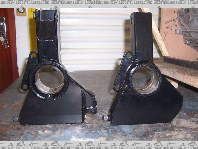
Thanks for the nice comments and exhaust info, i will add the balance pipe before the mufflers, it will run across above the back of the bell housing. As for my rear uprights, my engineer feels that he can skim them out to specs. Failing that I may just revert back to the original Subaru housings. They could easily do the part even though the toe control would be `different`. Terry, I did not cut corners with weight and built them from 4mm plate which i had folded to the shape and then cut and ground them to fit. The job would have been easier if I had used 3mm for definite. I turned up the centre bosses and then welded the laser cut brake mount which included a ring around the boss for accurate location onto a step cut on the boss giving correct caliper location, all that was easy! Big mistake was underestimating shrinkage from the welding. If i did this again, i would change my process to only roughing out the inside bearing area and then making a jig /plate that supported the entire assembly in the lathe and AFTER all the welding was done, then do the final bearing and seal cuts meaning no shrinkage. I will now make up that jig plate and hope that there is enough meat to work with. It will mean some careful set up before cutting.
As for weight, try 4 kg each versus the origional Subaru ones at 3.5kg. I think also that I may in the future look to other drive systems such as Nissan because there bearing bolts in, meaning that welding fabrication is not so critical. I can not change now because i have my wheels on hand.
Other news is that I have sold our McCopy mk11 Lotus! V8 as it did not get used during the winter and Carol and I got burnt to a crisp last summer from the sun and wind burn.
First to see bought it so I am now looking to buy a nice MX5 where we can choose the exposure to the elements.
Off for a few days r&r now.
Happy new year...its been a while since i posted, went to help my brother for a couple of weeks and 3 months later we are almost finished setting up a new shop and transferring about 500 rolls of carpet to a new warehouse, this retired lark is hard work.
Work on the car just stopped because when i got home from doing 11 or 12 hours, my gas tank was plain empty. Any how it provided good funds to progress the car with new Hoosier`s being delivered next week and a whole lot of other goodies now sitting in the cupboard including a Craig Davies electric water pump and all the gauges ect.
I have have just spent the last few days getting back into build mode and planing my next steps as I have committed to running 4 twin choke down drafts again which means make another set of inlet manifolds...more work! Given this direction, a new timing chain gears seemed to just cry out for a new cam...so Mr Summit delivered me a new med cam and I sourced Rover hyd. lifters locally. Went to pick apart and extracted a nice small Diahatsu alternator which got mounted yesterday, driven by a modified Subaru bottom pully mounted on the back of the Rover crank damper.
One task that did get completed before Christmas was the mx5 version of my rear uprights, this time i roughed them out before welding and then got the bearing areas turned out later. These have worked out well and I know that should I need to do mk3`s then I could do even better. The Subaru bearings went in nice and snug so final job will be to cut some axels...Subaru outer to Audi inner.
The rear suspension wish bones are made along with most of the radius rods and top arms so have now ordered the shocks and springs from Summit. Dummied up the roll bar today and it seems like the diagonal brace between the rear back supports will clear with the carbs. I am at the stage now where you think the chassis is completed yet dare not throw any paint at it...yet. I will leave the motor fresh up until last. Finally found some cross section drawings of the M8B and have gathered up enough sheets of custom wood for the 9 profiles, really can not start the mould work until chassis is all done. Between times we have had the motor home out and away and been for a few pleasant drives in the MX5...LIFE IS GOOD.
Sadly its back to work on Monday for about another month so my illicit stash will be quite healthy.
Regards
All
Russell
Attachments
Last edited:
Nice to see some good progress Russell, happy new year to you too.
Cheers
Fred W B
Cheers
Fred W B
Russel nice uprights, I am surprised it is only 4 KG I had thought about fabricating some uprights but assumed it would be lighter in a casting.
Looking at what you have made 3 to 3.5 kg would not be hard.
Well done.
Jim
Looking at what you have made 3 to 3.5 kg would not be hard.
Well done.
Jim
Howard Jones
Supporter
What if the bearing tube was left long, say a couple of inches, so that it could be chucked up in a lathe. Then the bearing bore could be trued and the extra length could be milled off after that. Do you see an issue doing it that way?
By the way the best build logs on this forum to learn something from are always the guys in New Zealand and Australia. Maybe because all the thinking is happening upside down.........great job all you guys!!!!
By the way the best build logs on this forum to learn something from are always the guys in New Zealand and Australia. Maybe because all the thinking is happening upside down.........great job all you guys!!!!
Howard
I thought i was clever first time and could weld without shrinkage or distortion!
I could have gripped the first ones in a 4 jaw but the massive distortion meant that they were very oval. This time not only did I make them lighter, but I also left enough of the boss protruding that I could easily 4 jaw them to the correct size. Prior to welding, I had turned up the outer grease seal landing and trued up both the outside and the inside of the inner bearing area so that final machining after welding was easy. Funny that this time around, these did not distort at all.
I had left the hub boss at around 10mm wall thickness and feel that if i did them again, I would thin down that hub boss more prior to welding and machining. Because I can not grip such a diameter as the whole assembly, I got a local engineer to do the final bearing bore and they did a nice job.
You may also notice that the brake caliper mount started out as a ring with lugs, this was to enable accurate location of that plate against a landing turned on the hub. This meant that welding up true was a simple task and then I cut off the surplus ring.
Russell
Attachments
Terry Oxandale
Skinny Man
Great job on the uprights Russell!
Similar threads
- Replies
- 2
- Views
- 427
- Replies
- 8
- Views
- 667
- Replies
- 16
- Views
- 2K
- Replies
- 0
- Views
- 689