Howard Jones
Supporter
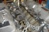
One of the things that occurs to me is that when using a reverse lower wishbone and trailing arms the rear upright is more complicated than a twin A arm/toe link layout would otherwise be.
The different pickup point widths at the top and bottom make the construction process more complicated it seams.
I do like the ring locating system you used for the caliper mount. Good innovative construction method. Most people don't realize just how much time goes into the "how". I know for me, once I have figured out "how" the do is usually pretty easy.
So what have you settled on for the bearing hub tube optimum wall thickness? How are you going to locate the bearing inside the housing? Are you using a spacer between the bearing internally? Or am I wrong about how that works?
Trying to learn something here, forgive my lack of detailed knowledge.