
You are using an out of date browser. It may not display this or other websites correctly.
You should upgrade or use an alternative browser.
You should upgrade or use an alternative browser.
McLaren replica build base on a Manta
- Thread starter blueovalz
- Start date
Terry Oxandale
Skinny Man
I agree, but it was the only ones I had. Without it, the joint was contacting the arm. I just ordered some 1/2" long spacers that are tapered so these new spacers have a lot of surface area on the arm side to help support the bolt.
That looks much better and the shorter tapered spacer will finish it nice. will be interesting to see how much movement there is in the turns as that bar looks pretty beefy, I'm thinking you want the rear pretty stiff and then work the front to it as a softer rear gives more under steer it depends on how you like your car to turn in. I have to come clean here as I have never driven mid engine cars so I tend to like a little over steer you can drive with the throttle but that's the Rally driver coming out. Fun times sorting it out.
The right tank is well underway and the left pontoon 2/3rds done, ran out of alloy sheet so have slowed my progress.
Keep the post coming
Cheers Leon.
The right tank is well underway and the left pontoon 2/3rds done, ran out of alloy sheet so have slowed my progress.
Keep the post coming
Cheers Leon.
Terry Oxandale
Skinny Man
It's a pretty soft bar (3/4" with long arms). Looking at our member's set-ups over the years, I'm going to mimic some of them with a larger bar up front initially. I'm looking to give it a good "general" tune in March. Like Leon, this mid-engined configuration is new to me, and I want to safely learn into the balanced set-up.
Terry Oxandale
Skinny Man
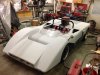
I'm just about finished with the bodywork, and being I'm planning on testing this at a road course in about a month, I'm in need of some side mirrors. Something similar in shape to the McLaren mirrors is preferred. So I purchased some cheap bullet mirrors, removed the base and fabricated a longer stem that somewhat resembles the McLaren base (using thin-walled streamlined tubing). After hammering the mounting plate to match the curves on the fender, welding material inside the stem to drill and tap for fastening both the mirror to the stem, and then the stem to the body, and then welding the plate and stem together, I ended up with this:


Terry Oxandale
Skinny Man
No paint before track day. Still in the 40-50 range here, and I've got a lot to do before putting it on the track, like fastening the roll hoop, addressing fire suppression, opening up the side scoops, etc.
If the metalwork was perfect, I'd chrome plate the mirrors, but that's not the case. I'll just do the "bodywork" thing on them and find some kind of metallic wrap or paint that gets as close as possible to the mirror finish. I don't want to paint them the same color as the body panels. In my mind's eye, the mirrors are a necessary evil in that you need them to drive safely, but they disrupt the beautiful lines of our cars. So not painting them the same color as the car hopefully will help in separating them visually from the body lines. I don't know if that makes sense or not, but that's my story and I'm sticking to it.
Finished the driver's side one this morning. Think I'll put the plates on it and take it for a spin around the neighborhood.
Last edited:
Terry Oxandale
Skinny Man
Make sense! Thanks Randy.
Terry Oxandale
Skinny Man
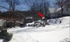
Everybody went to the track but me. 1/2" of ice and snow on the 1000' of road in front of my house, at a pretty steep grade, prevented me from getting the car out of the neighborhood (arrow was where I needed to get to in order to get back down to the main road).
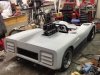
Anyway, our weather here is getting warm enough to be scheduling some time off for painting this thing. I've had two recent test-drives of about 30 minutes each without the vapor-lock issues I've been having, but I still have some pretty warm fuel and fuel rails. I've observed the fuel boiling in the swirl-pot (can hear it percolating, plus feel the vibrations on the case), with the attendant loss of fuel pressure at the injectors. So I opened the side scoops (I was going to do that anyway, eventually) and fabricated ducting that would force fresh air into the engine bay, with an emphasis on the swirl-pot. I also added some shielding with thermal barrier applied to the shielding to protect the pot from radiated header heat. Lastly, I have the water pump, plus the fuel pump, located in a small compartment in the passenger side-pod, fully enclosed with no ducting. I opened that compartment up with a 70mm intake tube at the front (inboard of the front wheel) using a small scoop to pull air from under the car, and slightly larger hole at the rear of the pod (with a muffin fan), to vent fresh air through this compartment. My thoughts were that the water pump's higher temperature was also contributing to the fuel warming situation (the Aeromotive A1000 pump plus two large fuel filters all in a small space with the water pump). With all of that done, I took the car out in 80+ degree weather this weekend, and only experience a very minor amount of leaning (would spit occasionally), so most the the problem has been resolved. The fuel rail is still very warm, so I have assembled a final attempt to cool that down by installing a Setrab cooler (120 X 120) in one of the side-scoop ducts, and then running the fuel through this before returning back to the fuel rails. My fuel re-circulates in two ways. From tank to pot and back, as well as pot to fuel rails and back. Obviously the tank to pot re-circulation is not enough to keep the fuel temperature down to a reasonable value. I'm glad I made my side scoops about 25% larger in frontal area than the McLaren had. This helps push more air into the engine bay.
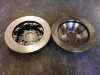
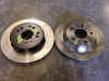
The last mechanical thing I've been working on is a more flexible brake system. Currently I'm using C4 Corvette rotors with Outlaw 4000 series calipers. Wilwood was not helpful in providing a correctly offset "kit" for these 12" X .800" rotors (they only provide assemblies for the 13" and up rotors, which won't fit in my wheels), so I perused their site and found an acceptable combination of hat and rotor that will fit within .040" of the current caliper position. This allows me to use different rotor designs as well as the 1.25" thick rotor (with a thick shim at the caliper) instead of the .810" rotor. So that is a work in progress. The photos show a comparison of the OEM C4 rotor vs the new Wilwood .810 rotors.
Anyway, our weather here is getting warm enough to be scheduling some time off for painting this thing. I've had two recent test-drives of about 30 minutes each without the vapor-lock issues I've been having, but I still have some pretty warm fuel and fuel rails. I've observed the fuel boiling in the swirl-pot (can hear it percolating, plus feel the vibrations on the case), with the attendant loss of fuel pressure at the injectors. So I opened the side scoops (I was going to do that anyway, eventually) and fabricated ducting that would force fresh air into the engine bay, with an emphasis on the swirl-pot. I also added some shielding with thermal barrier applied to the shielding to protect the pot from radiated header heat. Lastly, I have the water pump, plus the fuel pump, located in a small compartment in the passenger side-pod, fully enclosed with no ducting. I opened that compartment up with a 70mm intake tube at the front (inboard of the front wheel) using a small scoop to pull air from under the car, and slightly larger hole at the rear of the pod (with a muffin fan), to vent fresh air through this compartment. My thoughts were that the water pump's higher temperature was also contributing to the fuel warming situation (the Aeromotive A1000 pump plus two large fuel filters all in a small space with the water pump). With all of that done, I took the car out in 80+ degree weather this weekend, and only experience a very minor amount of leaning (would spit occasionally), so most the the problem has been resolved. The fuel rail is still very warm, so I have assembled a final attempt to cool that down by installing a Setrab cooler (120 X 120) in one of the side-scoop ducts, and then running the fuel through this before returning back to the fuel rails. My fuel re-circulates in two ways. From tank to pot and back, as well as pot to fuel rails and back. Obviously the tank to pot re-circulation is not enough to keep the fuel temperature down to a reasonable value. I'm glad I made my side scoops about 25% larger in frontal area than the McLaren had. This helps push more air into the engine bay.
The last mechanical thing I've been working on is a more flexible brake system. Currently I'm using C4 Corvette rotors with Outlaw 4000 series calipers. Wilwood was not helpful in providing a correctly offset "kit" for these 12" X .800" rotors (they only provide assemblies for the 13" and up rotors, which won't fit in my wheels), so I perused their site and found an acceptable combination of hat and rotor that will fit within .040" of the current caliper position. This allows me to use different rotor designs as well as the 1.25" thick rotor (with a thick shim at the caliper) instead of the .810" rotor. So that is a work in progress. The photos show a comparison of the OEM C4 rotor vs the new Wilwood .810 rotors.
Attachments
Last edited:
Terry - just a quick thought on your fuel vapor issues.. We had a problem with the high flow of the Aeromotive pumps on a race team I was on. Two things actually;
1) The return line from the regulator was too small (#4) and provided sufficient restriction to cause the fuel pressure to continually rise well beyond the max pressure we set at the regulator. The flow through the return line was of substantial force.
2) The return line was dumping in at the top of the fuel cell and was more of a pressurized spray that atomized within the cell and some (much) fuel was lost in the venting of the cell to the atmosphere.
We did three things.
1) Moved the regulator to be joined to the output side of the pump, thereby running only regulated pressure forward to the fuel rail.
2) Increased the size of the fuel return line to #8
3) Put a discharge tube in the cell to route the incoming fuel from the return line to the far side of the cell at the bottom. Therefore reducing the amount of atomization dramatically.
These efforts all worked very well and were repeated on the other three cars in our team.
On the atomization -
It was actually so bad that on one race day in Texas, we scarcely made 15 laps of a 50 lap race before the car actually ran out of fuel. Mind you it had 30 gallons of 102 octane when it left the paddock. It went three parade laps before the green flag and the driver was moving up from mid-pack when it crapped out... Quite embarassing for a race that was being televised..
Food for thought anyway...
Last edited:
Terry Oxandale
Skinny Man
Thanks Randy. My return line from the injector loop (at the regulator) is a -6 line, which goes into the pot at about the middle of the pot's sidewall (fully submersed). So perhaps that is enough. Aeromotive states that a -8 into the loop, and -6 out of the regulator, is a good size or capacity for my application (with a -10 going to the pump itself). Listening to the swirl pot "make coffee" (even up to 5 minutes after everything was shut off) was a bit concerning, but it appears with the extra air flow I've got now, the severity of the fuel temperature has been reduced quite a bit. I'd sure like to see if some kind of scoop under the engine area could be designed to be effective without hanging below the bottom plane of the floor. Considering our weather here hasn't even gotten hot yet, I'm worried about what's in store for August.
It is interesting to note that the other day, I inadvertently closed both return valves back to the gas tanks, which basically dead-headed the Holley low pressure pump, thus pressuring the swirl pot to about 7 psi. I didn't have the boiling in the pot, but did have another issue. Anyway, as soon as I recognized my error, I opened one of the valves to relieve the pressure back into the gas tank, and the pot immediately started boiling.
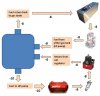
The attachment is a very simplified version of my set-up without the filters, one-way valves, diverter valves, 2nd gas tank or pump, etc.
It is interesting to note that the other day, I inadvertently closed both return valves back to the gas tanks, which basically dead-headed the Holley low pressure pump, thus pressuring the swirl pot to about 7 psi. I didn't have the boiling in the pot, but did have another issue. Anyway, as soon as I recognized my error, I opened one of the valves to relieve the pressure back into the gas tank, and the pot immediately started boiling.
The attachment is a very simplified version of my set-up without the filters, one-way valves, diverter valves, 2nd gas tank or pump, etc.
Attachments
Last edited:
Thanks Randy. My return line from the injector loop (at the regulator) is a -6 line, which goes into the pot at about the middle of the pot's sidewall (fully submersed). So perhaps that is enough. Aeromotive states that a -8 into the loop, and -6 out of the regulator, is a good size or capacity for my application (with a -10 going to the pump itself). Listening to the swirl pot "make coffee" (even up to 5 minutes after everything was shut off) was a bit concerning, but it appears with the extra air flow I've got now, the severity of the fuel temperature has been reduced quite a bit. I'd sure like to see if some kind of scoop under the engine area could be designed to be effective without hanging below the bottom plane of the floor. Considering our weather here hasn't even gotten hot yet, I'm worried about what's in store for August.
It is interesting to note that the other day, I inadvertently closed both return valves back to the gas tanks, which basically dead-headed the Holley low pressure pump, thus pressuring the swirl pot to about 7 psi. I didn't have the boiling in the pot, but did have another issue.That would be expected since raising the pressure would also raise the boiling point. Anyway, as soon as I recognized my error, I opened one of the valves to relieve the pressure back into the gas tank, and the pot immediately started boiling.
The attachment is a very simplified version of my set-up without the filters, one-way valves, diverter valves, 2nd gas tank or pump, etc.
I would suggest returning the fuel from rail pressure regulator to the tank/s, not the swirl pot, therefore removing any air/boiling fuel/ cavitation from being re- introduced to the high pressure section, plus the longer effective return loop into/thru the tank volume will lower the overall fuel temp.
With reference to temps in the engine bay look hard at getting hot air out rather than cold air in, some tuft testing with a video camera will help with this, amazing where air flow sometimes does not want to go.
Last edited:
Terry Oxandale
Skinny Man
I would suggest returning the fuel from rail pressure regulator to the tank/s, not the swirl pot, therefore removing any air/boiling fuel/ cavitation from being re- introduced to the high pressure section, plus the longer effective return loop into/thru the tank volume will lower the overall fuel temp.
With reference to temps in the engine bay look hard at getting hot air out rather than cold air in, some tuft testing with a video camera will help with this, amazing where air flow sometimes does not want to go.
That sounds perhaps doable, but I'll need to perform an accurate assessment of flow differences between the LP and HP pumps. My concern would be that the HP pump would empty the pot faster than the LP pump would fill it. Right now, I am skeptical that the LP pump outflows the HP pump, which is probably the reason I closed that circuit (HP) around the pot. Lastly, if the tank pickup becomes exposed, the amount of WOT time before emptying the pot will be drastically reduced. Perhaps a means of splitting the return so that some returns back to the pot, and some returns back to the tank. This would at least recycle some of the cooler fuel.
Last edited:
Terry Oxandale
Skinny Man
That's what hurts. My LP side has multiple "restrictions" in 90 corners rather then tube bends, diaphragm valves, and filters. Good input. Thanks guys.
All that white stuff looks very pretty and it looks like it was a beautiful day, shame you couldn't get out of the street. sounds like you are getting on top of your fuel issues, I have seen Dry Ice coolers used on race cars to battle temp problems but not practical on a street car. Its not an issue I have ever had to deal with so I hope it doesn't become one with this car. Looking forward to paint. Cheers Leon
Ian Anderson
Lifetime Supporter
Thanks Randy. My return line from the injector loop (at the regulator) is a -6 line, which goes into the pot at about the middle of the pot's sidewall (fully submersed). So perhaps that is enough. Aeromotive states that a -8 into the loop, and -6 out of the regulator, is a good size or capacity for my application (with a -10 going to the pump itself). Listening to the swirl pot "make coffee" (even up to 5 minutes after everything was shut off) was a bit concerning, but it appears with the extra air flow I've got now, the severity of the fuel temperature has been reduced quite a bit. I'd sure like to see if some kind of scoop under the engine area could be designed to be effective without hanging below the bottom plane of the floor. Considering our weather here hasn't even gotten hot yet, I'm worried about what's in store for August.
It is interesting to note that the other day, I inadvertently closed both return valves back to the gas tanks, which basically dead-headed the Holley low pressure pump, thus pressuring the swirl pot to about 7 psi. I didn't have the boiling in the pot, but did have another issue. Anyway, as soon as I recognized my error, I opened one of the valves to relieve the pressure back into the gas tank, and the pot immediately started boiling.
The attachment is a very simplified version of my set-up without the filters, one-way valves, diverter valves, 2nd gas tank or pump, etc.
What valves are you using - I found a number that should have been able to flow a lot but they ended up being exttremely restrictive
I'd look at the valves first
Ian
Similar threads
- Replies
- 9
- Views
- 777
- Replies
- 1
- Views
- 360