
- Forums
- GT40 Replica Manufacturers' Corner
- RCR Forum - RCR40/SLC/917/Superlite Aero
- The SLC Clubhouse
You are using an out of date browser. It may not display this or other websites correctly.
You should upgrade or use an alternative browser.
You should upgrade or use an alternative browser.
Frank Clark
Supporter
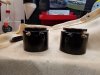
Alex, sorry you had bad luck with them. We've used tons of the Wilwood ones - literally 50 or so over the last 3 years. No issues. Have a whole box of spare Wilwood reservoirs (large and small) if someone needs one (or 10) - shoot me a PM.
I have spares from some other projects since they always send both sized reservoirs and I have yet to have one leak.
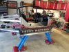
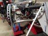
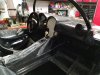
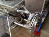
Had a list for the weekend and ended up getting it done between Friday and Saturday. Routed the heat and AC hoses to the panel I made in the rear, now just waiting for final termination and then putting in the motor to connect. Also got the passenger side radiator tube run. Installed the shifter, installed the drain for the AC unit, made some brackets to hold the ends of the brake lines where the flex hoses connect, mounted the AC condenser, routed all the rest of the AC hoses in the front, mounted the roll bar, mounted the rest of the fuel system and made sure I have all the fittings and hardware I need for final assembly. Need to make one more order of SS fasteners to replace a few places where I used CS for fit check. Also will be working to finish crimping the AC lines and finishing the dressing of the bundles.
Debating what to do next as I don't yet have my wiring harness (ordered it with my car and Fran is still waiting on ISIS for it) and I really want to have the rough routing done before I blow it all apart and spray on the Lizard skin. I have a few tasks left like cleaning up some of the brackets I made and need to give the interior some thought with respect to gauges, audio and finishes. I added some pictures below.
Actually this gives me some time to rest with the holidays coming and my daughter coming home from school next week, so its not all bad. Too bad the lulls come when the weather is cool and its not sweltering hot in the garage.
Attachments
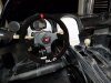
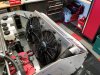
Mike - take a look at your residual valves. It looks like your front valve is reversed. Turns out there are a batch of valves out there that are incorrectly identified. The arrow *should* point in the direction of flow, but mine were reversed. The last pic of your post above showing the condenser install looks like the front valve is in the same orientation as mine - bleeding didn’t go well for me! I discuss my findings in my latest blog post.
Well, there is something to be said for getting up early on a Saturday being able to get some work done on the car before anyone gets up.
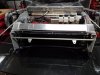
Started with the bulkhead panel in back of the fuel cell. When I went to the metal store on Friday, found some drop aluminum sheet in 2x4 sizes and picked up a couple.
Turns out that the way I am working the bulkhead, 48" covers the back of the fuel cell, and then I wanted a second removable piece to cover the opening on the drivers side by the fuel cell fittings. Cut the two pieces and mounted them in place - still have some trimming to do for final fit of the fuel filler, and will need to put some holes in the small panel so it can be removed to access the fuel filter.
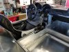
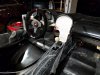
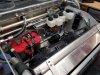
Then I moved my attention to the interior, trimming the console and the interior tub. The tub was all the way forward and the tire clearance was insufficient, so I trimmed the tub to move it forward about 1/4". Also trimmed the console to clear the AC unit under the dash. I had made a mount for the shifter, and painted that earlier in the week so got that installed today, and trimmed the tub and all of the panels so the shift cable can make it out the back.
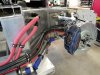
Finally, I opened the box with the engine management wiring and pulled out the chassis harness. Redressed the harness and the cable is plenty long enough for the drive by wire to reach the throttle pedal without having to extend the cable - the engineers at Chrysler were very concerned when I first said I was going to lengthen the cable, but as it stands it fits fine. Mounted the power panel on the passenger side in back of the fuel cell on the bulkhead, and will mount the PCM next to the fuel cell on the chassis as I have seen many of the LS engine management systems.
And all of that before the baking of the Christmas Cookies began. So now I am resting inside, already tasted two types of cookies, and waiting on the fudge. House smells really good right now so I think I will stay inside the rest of the night!
Started with the bulkhead panel in back of the fuel cell. When I went to the metal store on Friday, found some drop aluminum sheet in 2x4 sizes and picked up a couple.
Turns out that the way I am working the bulkhead, 48" covers the back of the fuel cell, and then I wanted a second removable piece to cover the opening on the drivers side by the fuel cell fittings. Cut the two pieces and mounted them in place - still have some trimming to do for final fit of the fuel filler, and will need to put some holes in the small panel so it can be removed to access the fuel filter.
Then I moved my attention to the interior, trimming the console and the interior tub. The tub was all the way forward and the tire clearance was insufficient, so I trimmed the tub to move it forward about 1/4". Also trimmed the console to clear the AC unit under the dash. I had made a mount for the shifter, and painted that earlier in the week so got that installed today, and trimmed the tub and all of the panels so the shift cable can make it out the back.
Finally, I opened the box with the engine management wiring and pulled out the chassis harness. Redressed the harness and the cable is plenty long enough for the drive by wire to reach the throttle pedal without having to extend the cable - the engineers at Chrysler were very concerned when I first said I was going to lengthen the cable, but as it stands it fits fine. Mounted the power panel on the passenger side in back of the fuel cell on the bulkhead, and will mount the PCM next to the fuel cell on the chassis as I have seen many of the LS engine management systems.
And all of that before the baking of the Christmas Cookies began. So now I am resting inside, already tasted two types of cookies, and waiting on the fudge. House smells really good right now so I think I will stay inside the rest of the night!
Attachments
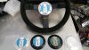
Well, finding ways to fill my time while I wait for my wiring kit. Have now plumbed the lift pump to the shocks (need to swap out the springs and install the hydraulic pucks before I can terminate the other end), mounted the recently received SL-C steering wheel (that is one nice looking unit) and done work on aluminum panels for the dash. After seeing the post last night with the new shifter, I am going to order the new gated unit so will have to undo some of my doing, but now is the time to get that done. Also worked most of the electrical for the Mopar engine harness which included wiring the fuel pumps, routing the wiring to the front for the clutch switch, installing a clutch switch (hydraulic) for the starter circuit. Also built all of the fuel lines using some hose I had left from my last hot rod project (it is amazing how much line you save when the fuel cell is a foot from the engine) and put a check valve in the vent line. Inside, I have the Koso gauge mounted, and have laid out how the other gauges and switches will fit in the center panel. I ordered some custom gauges from Speed Hut which roughly match the style of pointer and font of the Koso gauge, and they even had a temp gauge that works off of the CAN Bus. They have a version with a warning light built in, but I will be using the temp light on the Koso unit so went with just a gauge. For you Chevy guys, they also have a CAN Bus driven oil pressure gauge, but I had to go with a traditional unit because they don't have the right interface for the Mopar system.They have a version that with warning. When I get them, I will post some pictures. In looking at the types of switches I want to use, I think I am going to order the inMotion module from Infinity box to run the lift pump, exhaust cut outs and have the option to use it for the door actuators if I go that route. Also doing some work on the brake calipers to get rid of the Chevrolet stamping, but haven't quite worked that out. I was going to go the powder coat route, and talked with the guys in south Florida who have done a few i have seen, but they want a lot of money and I am having a hard time getting my head around spending it. Posted some pictures of the progress below. Hopefully will get some more done this weekend.
Attachments
That steering wheel looks nice! Mine didn’t come with a center button - is it a horn switch or just a beauty cover?
On powder coating - I did a pretty nice job despite my zero experience using the eastwood dual voltage powder coat kit. It’s definitely an intro level kit but it’s fine for doing calipers. If you want just a single solid color I think you’d be able to do it yourself just fine. I laughably attempted an orange candy for my calipers - basically the hardest combo you can do. Luckily it turned out ok. Results would have been better if I did a single stage solid color.


If you care to read more about my experience I have a post here:
13. Braking the silence – Cam's Superlite SLC
On powder coating - I did a pretty nice job despite my zero experience using the eastwood dual voltage powder coat kit. It’s definitely an intro level kit but it’s fine for doing calipers. If you want just a single solid color I think you’d be able to do it yourself just fine. I laughably attempted an orange candy for my calipers - basically the hardest combo you can do. Luckily it turned out ok. Results would have been better if I did a single stage solid color.
If you care to read more about my experience I have a post here:
13. Braking the silence – Cam's Superlite SLC
The center button is a horn. The only problem I had with the steering wheel was getting it to fit on the NR-G hub. The hub I was using was a 6 hole but the SL-C wheel is 5 - i bought a second 5 bolt hub for this wheel but there aren't many options.
I have looked into doing powder coating myself but never quite could get myself to do it. But yours look great so maybe it is time to add that capability to the shop.
I have looked into doing powder coating myself but never quite could get myself to do it. But yours look great so maybe it is time to add that capability to the shop.
Ron McCall
Supporter
PeteB
GT40s Supporter
Just ordered carbon seat, door cards and the new shifter. Can't wait to get the interior together
I'm anxious to see what the new shifter looks like actually mounted in a SLC. Looking forward to your updates when you get it.
Another productive day. Had a list for the weekend and almost got it done today. Started with cutting off those long threaded stubs on the rear hubs so the wheel caps will fit. Then finished up the lines for the front hydraulics, routing the lines, adding cushion clamps and putting on the ends for both sides. Also added bleeder screws to the second port of the puck so I can bleed the system a little easier.
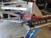
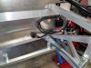
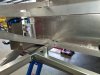
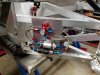
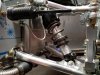
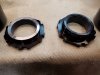
I am still pondering the orientation of the shocks and hydraulic pucks. I have seen pictures with the puck on the bottom, but understand the limitations of that. Have also seen the puck on top with the shock inverted, but in this configuration the adjusting ring needs to be turned down so it fits flush on the puck (like Cam shows in his blog, post 11). A second configuration is to leave the shock with its normal orientation and move the puck to the top. In this way, the top of the puck engages the top cone of the shock and fits flush with no machining necessary. Each seems to fit fine, and I have both configurations on the car now, but will need to decide which way to go. Will also have to decide if I am going to get the helper springs to keep the spring centered in no-load situations. When I talked to Fran last month at the shop, he didn't seem to think this was a necessity. Have a picture of each attached.
Moving on, I am going to have carpet in the forward sections of the two footwells and below the seats, and got those roughed today (have some carpet left over from the same project that had left over braided line for the fuel system). I also got the aluminum cut for the fan shroud - will get that bent up tomorrow.
Feels good making progress. Just about ready to take it all apart and get on the sound and heat coatings, just waiting on the wiring harness. Tomorrow will be getting the fan shroud done and a couple other miscellaneous items.
Attachments
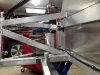
Spent a brisk 41 degree morning in the garage - actually felt quite nice. After bending up my fan shroud, I got it partially installed and the fans mounted. It is made out of .060 AL sheet and with all of the bends is quite rigid. Will work the mounting on the bottom when I take the car apart for cleaning and coating.
Also have the carpeting now roughed in on both sides so once it is going together, I can get that installed before the tub goes down.
Also have the carpeting now roughed in on both sides so once it is going together, I can get that installed before the tub goes down.
Attachments
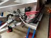
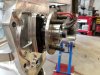
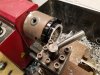
Therapy session with the lathe tonight. Decided to invert the shocks but as Cam has shown in his blog, the adjusting nut which then gets inserted into the puck needs to be shortened to ensure the weight of the car doesn't ride on the inner lip. While the spacer that comes with the lift kit has a lip that is only .300" tall, making the adjuster that size would require removing over a quarter of an inch, which also reduces the number of threads. Since the pocket in the puck is .370" deep, and the shim is .032", I shot for machining them down to .380". This ensures at least .022" of gap between the end of the spacer and the ridge inside the puck so I can be sure the weight is on the shim.
If you are doing this yourself, it is pretty easy and I did it on the micro lathe that I keep in my garage. Due to the wide thread pattern, I ended up with a pretty big burr at the end of the last thread, but I took care of that when I put the chamfer back on ID and OD. Put some pictures below of the process including one of the finished installed package.
If you are doing this yourself, it is pretty easy and I did it on the micro lathe that I keep in my garage. Due to the wide thread pattern, I ended up with a pretty big burr at the end of the last thread, but I took care of that when I put the chamfer back on ID and OD. Put some pictures below of the process including one of the finished installed package.
Attachments
Nice work! If you think about it that adjuster you’re machining doesn’t carry the majority of suspension loading. You use the upper and lower and tighten against each other, the upper serving as the jam nut. When you tighten the two relative to each other the upper adjuster preloads the threads on the same side that gets loaded as suspension loads increase. The lower adjuster’s threads are first preloaded on the side opposite - so as suspension loads increase you actually decrease the stress on those threads before they start loading up again. In short, modification of the lower adjuster by turning it down really doesn’t negatively impact the load carrying capability of the assembly, at least not enough to make a difference. IMHO of course.
Frank Clark
Supporter
I inverted my shocks as well. Did not have to shorten the adjuster nut. It’s been a while, but I think I turned the rams instead. In any case, some minor machining is necessary. I also changed to 2.25” diameter springs.