Doc Watson
Lifetime Supporter
Yes that was what I was suggesting... although triangle bracing on the lower sill would be good, and please don't take anything I said as criticism of what you are doing, sounds like a great project.

@Neil,
I still have no idea what type of axle I should use.
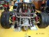
At the moment I tend to use a normal double wishbone arrangement with additional guide strut.
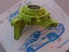
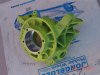
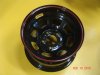
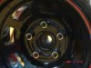
I will try to use the same wheel mounts on all four wheels.
Do you have some information about your suspension for me?
Never going to work with that Chevy in there.
")
Lozenging basically means the square cross section of the side pod becomes a parallelogram. It's not clear to me, but I thought I'd raise the question. If FEA is not available, building a scale model out of balsa wood might give you indications. Edit didn't see the most recent posts, subject covered.Tom, what do you mean by "lozenging"?
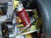
at the moment I only see the advantage of the big sidebox in relation to the tank.
The solution with the 45° struts is lighter, but offers hardly any space for a tank, especially if it should be removable.
I once sketched a solution where the tank can be removed to the rear when the cross strut (red) is screwed on.
Pink is the tank, grey are crash elementsView attachment 106231


