Nice! I like the mesh over the air intakes. I must admit I'd considered if it was possible to fit air filters in them, seal it against the carbs and run the entire thing as an airbox. If I don't attempt that I think I'll be doing the same and use mesh to prevent ingestion of stones, birds and small children.

You are using an out of date browser. It may not display this or other websites correctly.
You should upgrade or use an alternative browser.
You should upgrade or use an alternative browser.
Norfolk Tornado
- Thread starter saxoncross
- Start date
Brett,
I’ll do you a set in return for a 9-hole grille made with your forming tool!!
David,
I think one of the builder on here has incorporated panel filters in this area, so it is possible
Regards
Andy
I’ll do you a set in return for a 9-hole grille made with your forming tool!!
David,
I think one of the builder on here has incorporated panel filters in this area, so it is possible
Regards
Andy
Brett James-McCall
Moderator
Izza deal, though you have to send me the dimensions of your opening on your rear clip...
You coming down to dyno testing any time soon?
You coming down to dyno testing any time soon?
+1 pls ")
Very Very Very nice work :thumbsup:
Very Very Very nice work :thumbsup:
Nice work Andy! Fancy making 2 sets")
A few more updates:
Andy
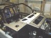
- The engine bay opening has now been increased width by ½” either side to give a better clearance to the fuel rails. A lot of fiddling for not a lot to show.
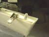
- A new front clam hinge bar fabricated. The aluminium end plates are stepped to clear the bolt head for the cross tube. The cross tube is made from some scrap thin wall tube I had, with a couple of short M8 screws welded into the ends for location. Ideally I’ll locate to the nylon bobbins to the body with a couple of pip-pins, but while I search for them they’re held with a couple of M6 screws.
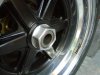
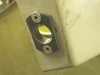
- The centre-lock wheel nuts needed for the IVA test have turned up. These were made to my design with a R3 on all external radii to meet the external projections requirements. These will eventually be hard anodised. I also designed a tool that will prevent the socket slipping off the nut when being done up.
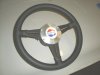
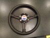
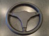
- Finally got the steering wheel I’ll use (14” Moto-Lita, black anodised) I still need to make a protective crash pad for the IVA test (which covers the holes in the spokes), but I couldn’t resist making the boss to go on post-IVA (will eventually be black anodised to match the spokes)
Andy
Attachments
A few more updates:
Regards
Andy
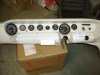
- The Smiths Gauges have arrived, including a 220mph electronic speedo. I don’t think I’ll ever reach that speed, but it’s a nice finishing touch.
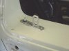
- Made up the internal release mechanism for the doors. These bits will eventually be anodised, however I’m still 100% happy with the release handle, so it may be re-designed.
- Made a start on fitting and aligning the body. The previous builder had incorrectly positioned the spider onto the chassis, meaning that it had given me a bum-steer of how it all fits. The front edge of screen was 12mm too far rear, meaning I could never seem to align the top of the doors and have an acceptable clearance to the front clam. The gaps are getting better, but still needs a lot of work. The Body alignment pins I’d previously made seem to work well
Regards
Andy
Attachments
A bit more;
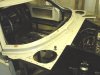
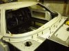
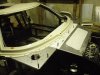
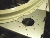
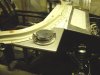
I’d always planned that I would bolt the front edge of the spider mounting onto the scuttle panel, as I think it looks tidier than the standard Tornado solution and it makes painting it a lot easier. However this can only be done after the spider is located relative to the doors/front clam.
The two forward bolt/clam supports (shown in first photo) are critical in temporary locating the front of the spider before the excess can be cut off. It’s further compounded by the fact that the Cleco’s are too tall to fit under the front clam to carry out the preliminary alignment checks. The finished solution is all now held together with M6 rivnuts, with the chassis being drilled & tapped where feasible. These can now be powder-coated to match the rest of the panelling
Access holes were also cut for the heater ducting, wiper motor & harness. It will eventually be made watertight with a 1mm closed foam sealing strip. As I’d previously fitted the filler caps, I had to check that they still cleared the front clam on closing – fortunately they did! In hindsight these should be fitted after the panels are preliminary aligned.
I’ve also added a couple of captive fasteners for the rear spider mounts into the chassis. This will allow the spider to be removed without the need to drop the fuel tanks for access.
Regards
Andy
Attachments
More stuff I’ve done recently;
I’ve had the steering boss black hard anodised (and the wheel nuts) and I’ve made an IVA friendly crash pad out of a piece of ABS, 10mm closed cell foam and a scrap piece of vinyl.
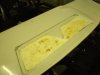
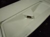
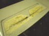
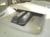
I’ve also sorted out the demist system. I’ve used Alfa156/Elise for the face vents, not strictly original, but blend in well with the rest of the dash. Connecting these was relatively straight forward once they had been shortened and angled to get the duct pipe on. I’d previously been informed that the demist function on a ’40 is not good at the best of time and considering the standard set-up, I’m not surprised. The screen demist moulding is effectively a defuser and hence slows down the air. What is required is a much smaller opening to keep the air velocity up, ideally an area smaller than the pipe feeding it (think of putting your finger over the end of a hose pipe!)
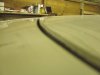
I started by filling in the plenum with expanding foam and then a suitable slot was cut into it. This will be covered with black duct tape (what else!) and eventually be hidden by a Ford Zephyr grille I picked up along the way
In the mean while I’ve been trying to get the body aligned. Door fit to the spider is OK, until I fit the door seal, which pushes the door above the spider profile. I’m now looking for a seal with a smaller profile, as I really don’t want to add ¼” of filler to the roof.
Happy Christmas to all current and prospective ’40 owners
Regards,
Andy
I’ve had the steering boss black hard anodised (and the wheel nuts) and I’ve made an IVA friendly crash pad out of a piece of ABS, 10mm closed cell foam and a scrap piece of vinyl.
I’ve also sorted out the demist system. I’ve used Alfa156/Elise for the face vents, not strictly original, but blend in well with the rest of the dash. Connecting these was relatively straight forward once they had been shortened and angled to get the duct pipe on. I’d previously been informed that the demist function on a ’40 is not good at the best of time and considering the standard set-up, I’m not surprised. The screen demist moulding is effectively a defuser and hence slows down the air. What is required is a much smaller opening to keep the air velocity up, ideally an area smaller than the pipe feeding it (think of putting your finger over the end of a hose pipe!)
I started by filling in the plenum with expanding foam and then a suitable slot was cut into it. This will be covered with black duct tape (what else!) and eventually be hidden by a Ford Zephyr grille I picked up along the way
In the mean while I’ve been trying to get the body aligned. Door fit to the spider is OK, until I fit the door seal, which pushes the door above the spider profile. I’m now looking for a seal with a smaller profile, as I really don’t want to add ¼” of filler to the roof.
Happy Christmas to all current and prospective ’40 owners
Regards,
Andy
Attachments
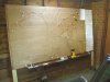
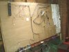
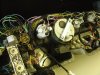
Well over the Christmas period, I finally made a start in manufacturing the wiring harness. It’s not one my favourite jobs, possibly why it’s taken me so long to get to get to this stage.
With all the electrical components positioned in the car, a simple skeleton harness was laid in the car made to establish the correct wire lengths. This was then was transferred to the build board. Although the harness could be laid up in the car, I didn’t fancy repeatedly being upside down in the cockpit trying to lay the wires in.
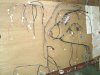
Separate drawings have been done of all the circuits and the harness will split into to 4 sections; engine, dash, front & rear clams, connected with weatherproof bulkhead connectors. It’s then protected by 4 Maxi fuses, 26 mini-fuses and 10 relays. This should be enough, assuming I’ve designed it properly.
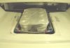
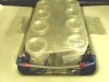
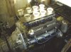
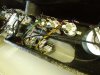
The air filters are finally fitted, mainly as I needed to position the air temp sensor (in the filter base plate) for the engine harness and it was good to know I’d got my calc’s correct for the clearance to the rear window.
Regards,
Andy
With all the electrical components positioned in the car, a simple skeleton harness was laid in the car made to establish the correct wire lengths. This was then was transferred to the build board. Although the harness could be laid up in the car, I didn’t fancy repeatedly being upside down in the cockpit trying to lay the wires in.
Separate drawings have been done of all the circuits and the harness will split into to 4 sections; engine, dash, front & rear clams, connected with weatherproof bulkhead connectors. It’s then protected by 4 Maxi fuses, 26 mini-fuses and 10 relays. This should be enough, assuming I’ve designed it properly.
The air filters are finally fitted, mainly as I needed to position the air temp sensor (in the filter base plate) for the engine harness and it was good to know I’d got my calc’s correct for the clearance to the rear window.
Regards,
Andy
Attachments
I’d previously been informed that the demist function on a ’40 is not good at the best of time and considering the standard set-up, I’m not surprised. The screen demist moulding is effectively a defuser and hence slows down the air. What is required is a much smaller opening to keep the air velocity up, ideally an area smaller than the pipe feeding it (think of putting your finger over the end of a hose pipe!)
I started by filling in the plenum with expanding foam and then a suitable slot was cut into it. This will be covered with black duct tape (what else!) and eventually be hidden by a Ford Zephyr grille I picked up along the way
I must admit I'd looked at it and thought similar, I've got a more modern edge vent (ie one that follows the windscreen line), if it'll fit the line of the screen I plan to use that instead, not sure what I'll then do with the existing 'vent' though.
Andy,
Looking good Andy.
Could you tell me where you got your air filters from and how you have fixed them to you throttle bodies? As I’m looking at this type of set-up for my Kinsler EFI system.
Best regards,
Chris.
Looking good Andy.
Could you tell me where you got your air filters from and how you have fixed them to you throttle bodies? As I’m looking at this type of set-up for my Kinsler EFI system.
Best regards,
Chris.
David,
I think if I hadn’t already sourced a Zephyr demister grille, I would have used a modern slot demister like you’re considering.
For the existing mould, I’d fill the void with expanding foam & roughly shape. A skim of filler will then give the desired shape to produce a simple mould (or left as the finished surface), from which an insert could then be produced for glassing in after the original section has been cut out.
Chris,
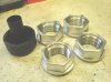
I got the filters from AT Power, who supplied my throttle bodies. They’re made by ITG and are the same ones used on the Cosworth DFV engines. On my throttles the base plate is clamped on the ramp pipes, as they top half with the bell mouth has a screw thread onto the lower section
Regards
Andy
I think if I hadn’t already sourced a Zephyr demister grille, I would have used a modern slot demister like you’re considering.
For the existing mould, I’d fill the void with expanding foam & roughly shape. A skim of filler will then give the desired shape to produce a simple mould (or left as the finished surface), from which an insert could then be produced for glassing in after the original section has been cut out.
Chris,
I got the filters from AT Power, who supplied my throttle bodies. They’re made by ITG and are the same ones used on the Cosworth DFV engines. On my throttles the base plate is clamped on the ramp pipes, as they top half with the bell mouth has a screw thread onto the lower section
Regards
Andy
Attachments
Still progressing with the harness build – this is taking hours! I’m using a 48 bulkhead connector for the dash, but I think I’m still going to need another connector as I won’t have enough pins. The power distribution is now sorted and I’m just working my way through the various circuits.
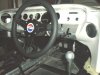
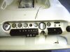
Although I’d previously positioned the indicator stalk in the dash, I’d never tried it with the steering wheel in place, as the splined adapter is a really tight fit and hadn’t yet made a suitable puller. Anyway when it was finally fitted the wheel rim clashed with the indicator stalk! This has resulted in the stalk being repositioned and a ½” spacer added to the steering wheel boss. Now it’s positioned to easily use and for major arm twirling exercises, it can be knocked into the high beam position to stop it from being clouted.
I’m currently musing over what the switch panels would look like with some carbon-fibre vinyl wrap applied. I’ll probably use it for the IVA and make a decision after this to powder-coat or anodise black.
Regards
Andy
Attachments
The main harness is just about finished and now needs fitting in the car for final termination of the rear fuse/relay block & ECU. These have to be done in the car as I know it won’t feed down the tunnel with the connectors fitted.
I managed to connect the dash using the single 48-way connector, the only exceptions being the blower motor (where an extra 12ft of wire would be needed instead of going straight from the switch to the motor) and the connections to the ignition switch.
An immobiliser has also been added for the IVA test, with meant lots of black wires have been spliced into the harness. I’ve used a Toad Sterling unit which is designed to disable 2 circuits. I’ve chosen the starter motor crank and the ECU (which in turn stops the HP pump). I’ve got the immobiliser unit on a separate multi-pin connector and I’ve made a separate connector with the key circuits bridged, so that I do the checks on the vehicle without the immobiliser hampering issues.
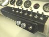
Finally a bit of Bling! – my new carbon fibre switch panels! OK so these are my originals wrapped with a carbon fibre vinyl. The result is better than expected, in fact I’m considering doing the whole dashboard in it and having the switch panels contrasting in either black satin powder-coat or black anodise. My only concern at present is that the vinyl I’ve got is too glossy and would reflect badly against the screen. Still musing over this, as this will be finished post-IVA. Rattle-can satin black with a splatter effect will do for now
Regards
Andy
I managed to connect the dash using the single 48-way connector, the only exceptions being the blower motor (where an extra 12ft of wire would be needed instead of going straight from the switch to the motor) and the connections to the ignition switch.
An immobiliser has also been added for the IVA test, with meant lots of black wires have been spliced into the harness. I’ve used a Toad Sterling unit which is designed to disable 2 circuits. I’ve chosen the starter motor crank and the ECU (which in turn stops the HP pump). I’ve got the immobiliser unit on a separate multi-pin connector and I’ve made a separate connector with the key circuits bridged, so that I do the checks on the vehicle without the immobiliser hampering issues.
Finally a bit of Bling! – my new carbon fibre switch panels! OK so these are my originals wrapped with a carbon fibre vinyl. The result is better than expected, in fact I’m considering doing the whole dashboard in it and having the switch panels contrasting in either black satin powder-coat or black anodise. My only concern at present is that the vinyl I’ve got is too glossy and would reflect badly against the screen. Still musing over this, as this will be finished post-IVA. Rattle-can satin black with a splatter effect will do for now
Regards
Andy
Attachments
Hi Andy,
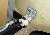
watching the fuel routing you did. It is the same way I did it with the two 90Degree Connector....While looking at it I was thinking if vibration can harm it over time ? What do you think...As said I did it the same way but not sure fit is the best way to do it ...
Maybe any suggestions from other readers?
Cheers
(C)arlos
David,
I think if I hadn’t already sourced a Zephyr demister grille, I would have used a modern slot demister like you’re considering.
For the existing mould, I’d fill the void with expanding foam & roughly shape. A skim of filler will then give the desired shape to produce a simple mould (or left as the finished surface), from which an insert could then be produced for glassing in after the original section has been cut out.
Chris,
I got the filters from AT Power, who supplied my throttle bodies. They’re made by ITG and are the same ones used on the Cosworth DFV engines. On my throttles the base plate is clamped on the ramp pipes, as they top half with the bell mouth has a screw thread onto the lower section
Regards
Andy
Hi Carlos,
if you're referring to the 2 90 degree connectors used to connect up the two fuel rails, I don't forsee any vibration or fatigue issues as they are designed for this type of enviroment.
Rgds,
Andy
if you're referring to the 2 90 degree connectors used to connect up the two fuel rails, I don't forsee any vibration or fatigue issues as they are designed for this type of enviroment.
Rgds,
Andy
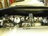
I’ve finally finished the dashboard wiring. The final harness wrapping will be done once all the continuity checks have been made. I’d previously bonded in a few brackets to the dash so the harness can be strapped to it and the wires to all the switches have deliberately been left long so that the switch panels can be pulled out. Although it hard to believe it taken me nearly 20 hours to wire this lot up!
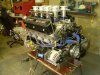
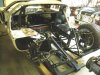
I pulled out the engine mainly over the weekend, mainly to fit the main wiring harness, but it allows lots of minor jobs to be done without the engine being in the way.
I’ve also purchased a central locking kit, which will installed post IVA, but the wiring will be added main vehicle harness before it’s fitted to the car, making the final installation easier. The last part of the electrical jigsaw is the engine harness and with the engine out, it also makes it a lot easier to make it.
Blimey – might even be in a position to start the engine this year!!!!
Regards
Andy
Attachments
Hi Keith,
You’re right wiring isn’t everyone’s cup of tea. I can do it, but I’m happier with more mechanical aspects of the build.
Regarding timing, I always knew this would take me around 5-6 yrs to achieve the standard of build I wanted, so being realistic where I am at present, engine start & final assembly this year and IVA early next year, I won’t be far off my original plan
I can’t believe the speed & quality of your build, but I’m only putting 8-10hrs a week into it and my philosophy of designing & making as much as possible leads to what others see as an unacceptably long build time.
Keep up the good work & I look forward to comparing notes when we get the finished ‘40s together
Regards
Andy
Similar threads
- Replies
- 4
- Views
- 2K